Photovoltaic systems, methods for installing photovoltaic systems, and kits for installing photovoltaic systems

a photovoltaic system and photovoltaic technology, applied in the field of photovoltaic generation of electrical energy, can solve the problems of increasing the cost of fossil fuels, affecting the appearance of buildings, and being heavy and bulky

Inactive Publication Date: 2014-02-11
CERTAIN TEED LLC
View PDF147 Cites 30 Cited by
  • Summary
  • Abstract
  • Description
  • Claims
  • Application Information

AI Technical Summary

Problems solved by technology

First, fossil fuels have become increasingly expensive due to increasing scarcity and unrest in areas rich in petroleum deposits.
Second, there exists overwhelming concern about the effects of the combustion of fossil fuels on the environment due to factors such as air pollution (from NOx, hydrocarbons and ozone) and global warming (from CO2).
While photovoltaic modules have been in use for some time, they tend to be heavy and bulky, and aesthetically unfavorable when installed on a roof.
These can be very advantageous, but can be difficult to install on steep surfaces, and can often result in incomplete coverage of the roof surface with photovoltaic power generation.
Moreover, fabrication and installation and connection of a plurality of smaller photovoltaic roofing elements can in some circumstances be a very slow, tedious, and costly process.

Method used


Image

  • Photovoltaic systems, methods for installing photovoltaic systems, and kits for installing photovoltaic systems
  • Photovoltaic systems, methods for installing photovoltaic systems, and kits for installing photovoltaic systems
  • Photovoltaic systems, methods for installing photovoltaic systems, and kits for installing photovoltaic systems

Examples


example 1

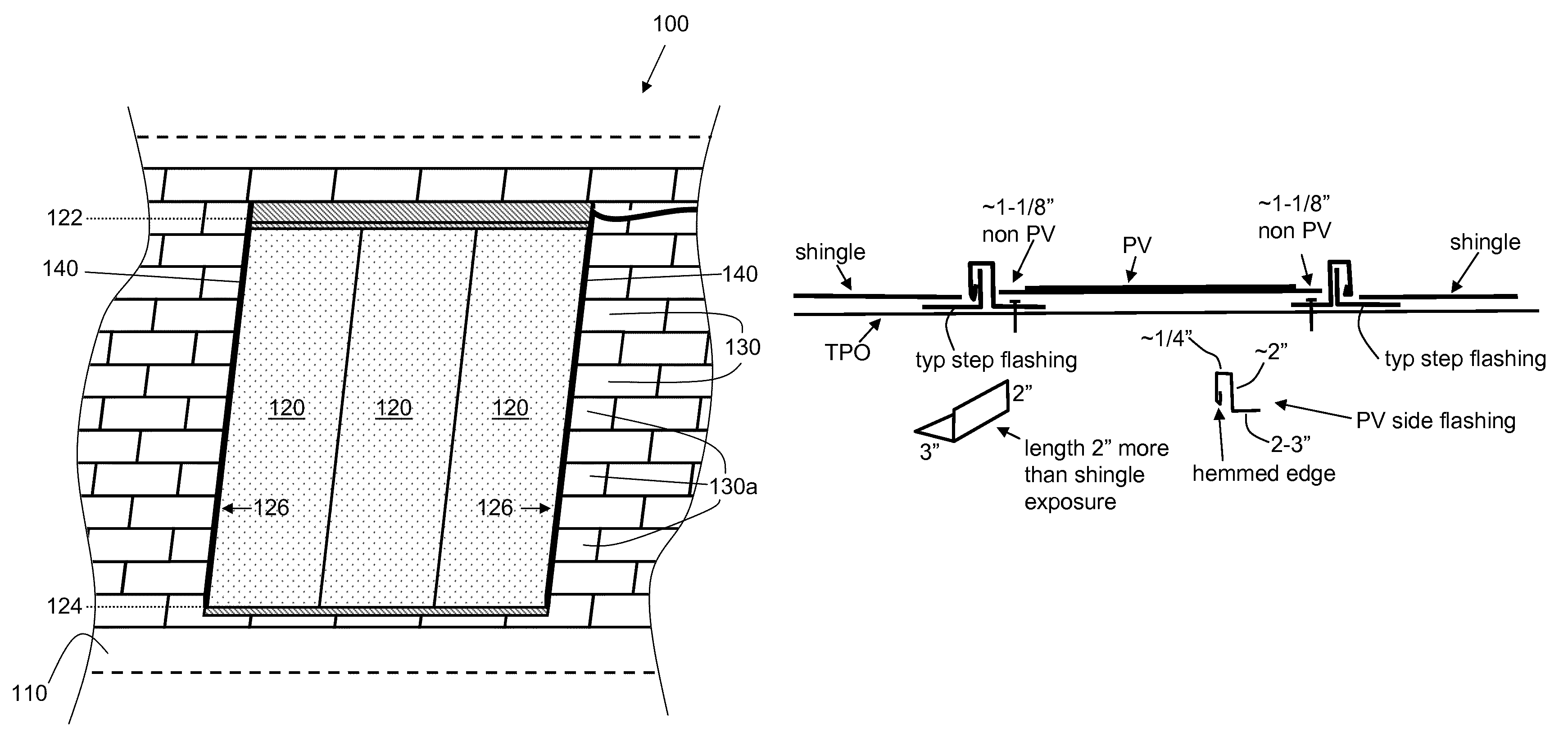
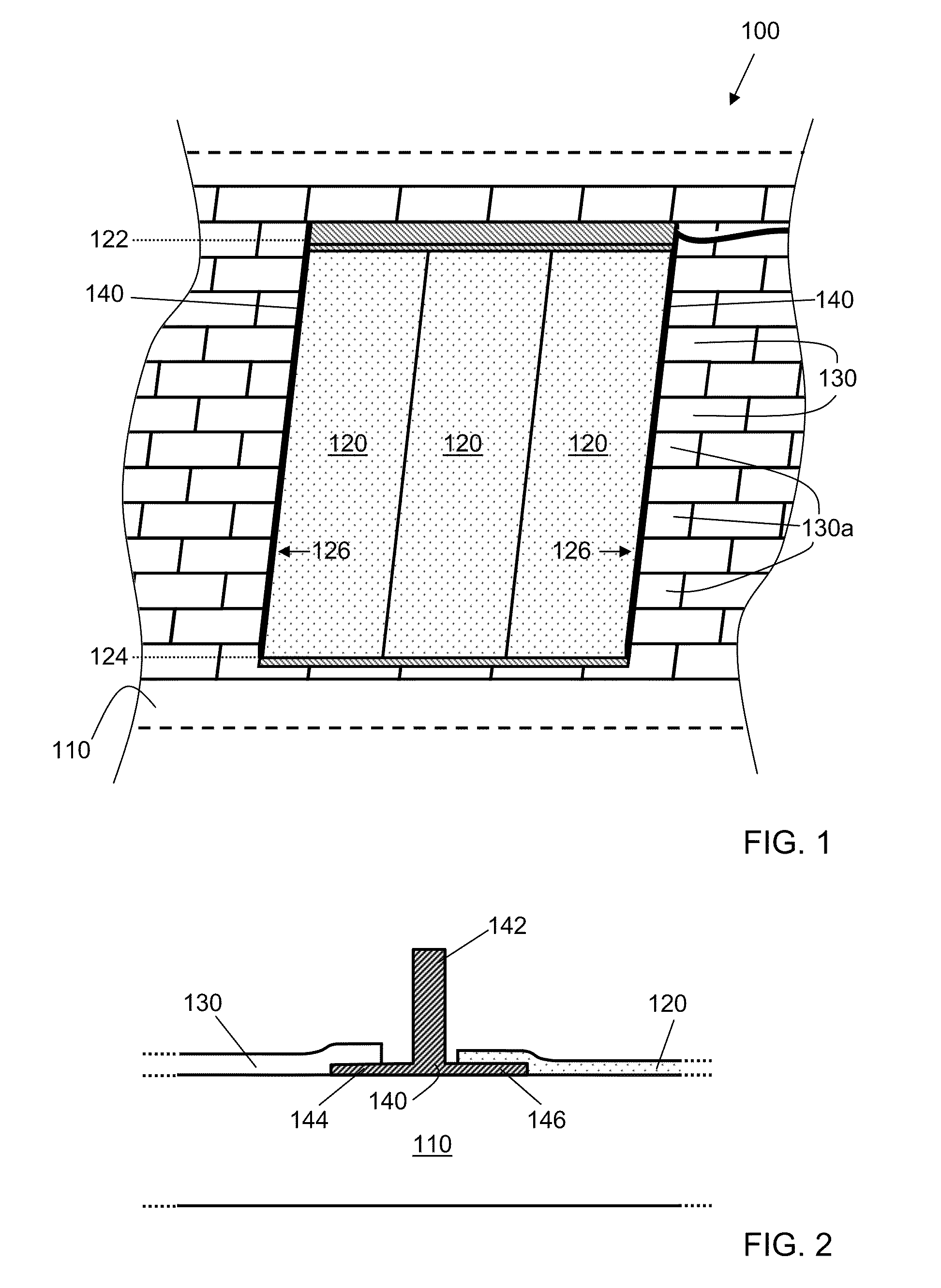
[0079 of a photovoltaic roofing system according to the invention uses as photovoltaic elements certain photovoltaic laminates, model PVL-68, available from Uni-Solar Ovonics. The roofing elements are 2-layer laminated architectural shingles, similar to those available from CertainTeed Corporation, and are conventionally installed on a roof deck. Coated aluminum flashings are bent to shape as described above, and nailed to the roof deck. A TPO membrane is placed between the PVL-68 photovoltaic elements and the roofing underlayment; the self-stick adhesive of the PVL-68 photovoltaic elements adheres them to the membrane. The interaction of step flashing with roofing elements is shown in FIG. 24.

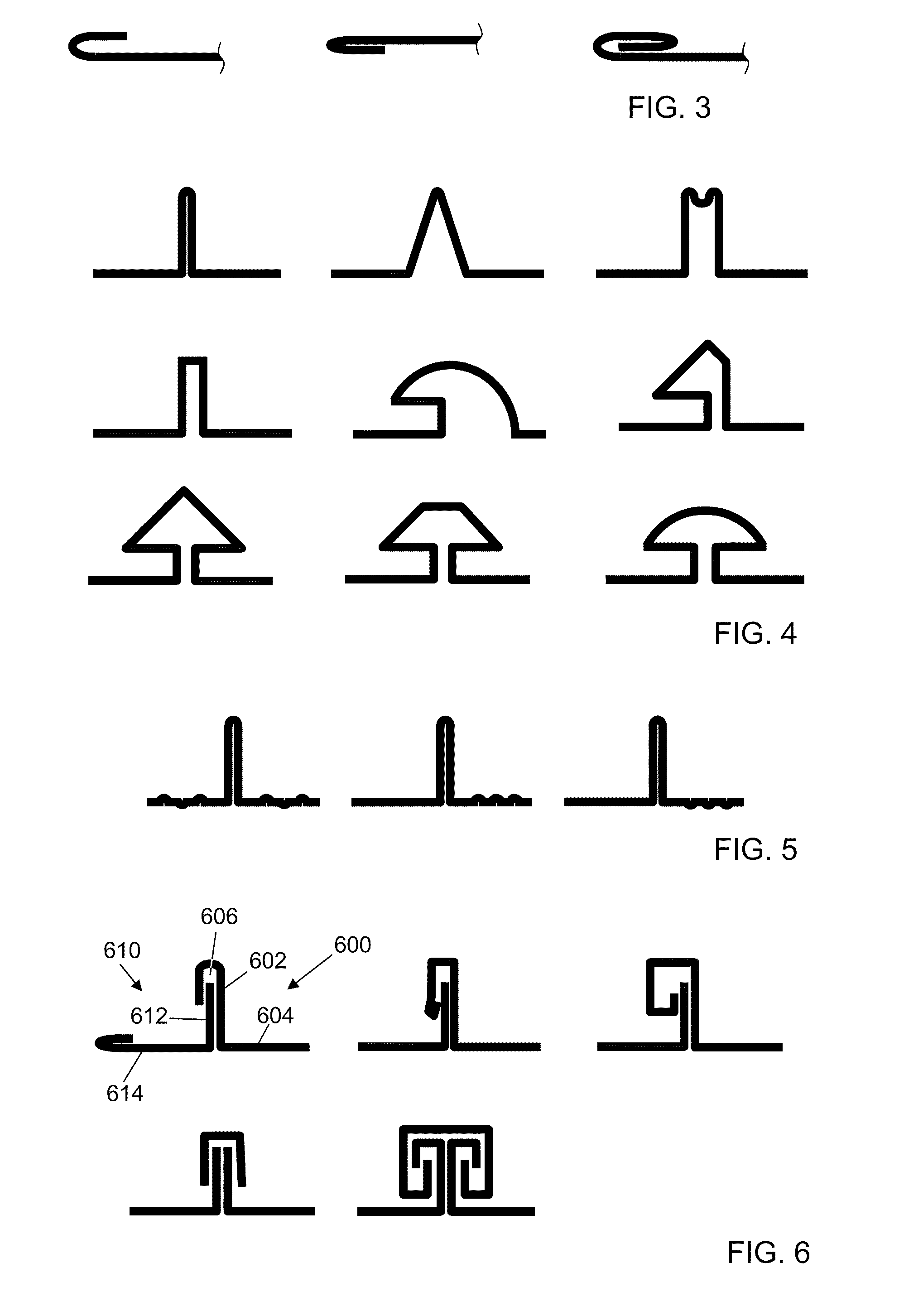
[0080]A set of flashings for the installation of Example 2 of a photovoltaic roofing system is shown in partial side perspective view in FIG. 25. The drawings of FIG. 25 are not necessarily scaled to one another. Bottom flashing 3610 has a hemmed return 3612 at its bottom edge (i.e., the edge ...


PUM


Abstract

The present invention relates particularly to photovoltaic systems for use in photovoltaically generating electrical energy. One aspect of the invention is a photovoltaic roofing system disposed on a roof deck. The photovoltaic roofing system includes one or more photovoltaic elements contiguously disposed on the roof deck, the contiguously-disposed photovoltaic elements defining a photovoltaic area; a plurality of roofing elements disposed adjacent the contiguously-disposed photovoltaic elements, along their side edges; side flashing disposed along the side edges of the contiguously-disposed photovoltaic elements, the side flashing having a cross-sectional shape comprising a vertically-extending feature and a flange extending from each lateral side at the bottom of the vertically-extending feature, with the flange facing the photovoltaic area being at least partially disposed between a photovoltaic element and the roof deck, and the flange facing away from the photovoltaic area being at least partially disposed between a roofing element and the roof deck.

Description

CROSS-REFERENCE TO RELATED APPLICATIONS[0001]This application claims the priority of U.S. Provisional Patent Application Ser. No. 61 / 162,950, filed Mar. 24, 2009, which is hereby incorporated herein by reference in its entirety.BACKGROUND OF THE INVENTION[0002]1. Field of the Invention[0003]The present invention relates generally to the photovoltaic generation of electrical energy. The present invention relates more particularly to photovoltaic systems for use in photovoltaically generating electrical energy.[0004]2. Technical Background[0005]The search for alternative sources of energy has been motivated by at least two factors. First, fossil fuels have become increasingly expensive due to increasing scarcity and unrest in areas rich in petroleum deposits. Second, there exists overwhelming concern about the effects of the combustion of fossil fuels on the environment due to factors such as air pollution (from NOx, hydrocarbons and ozone) and global warming (from CO2). In recent yea...

Claims


Application Information

Patent Timeline
Patent Type & Authority Patents(United States)
IPC IPC(8): E04B7/00E04D13/14E04D13/18
CPCF24J2002/5294Y02E10/50Y02B10/20Y02B10/12H01L31/0422F24J2/045H01L31/0482H02S20/23H02S20/00F24J2/5201H02S20/25F24S2025/014F24S2025/601F24S20/67F24S25/00F24S2025/021Y02E10/47Y02B10/10
Inventor JENKINS, ROBERT, L.
Owner CERTAIN TEED LLC
Why Eureka
Try Eureka