
Cutting tool and double-ended cutting insert therefor

a cutting tool and cutting insert technology, applied in the field of cutting tools, can solve the problems of undisturbed chip formation during the cutting process

Active Publication Date: 2014-02-11
ISCAR LTD
View PDF21 Cites 24 Cited by
  • Summary
  • Abstract
  • Description
  • Claims
  • Application Information

AI Technical Summary

Benefits of technology

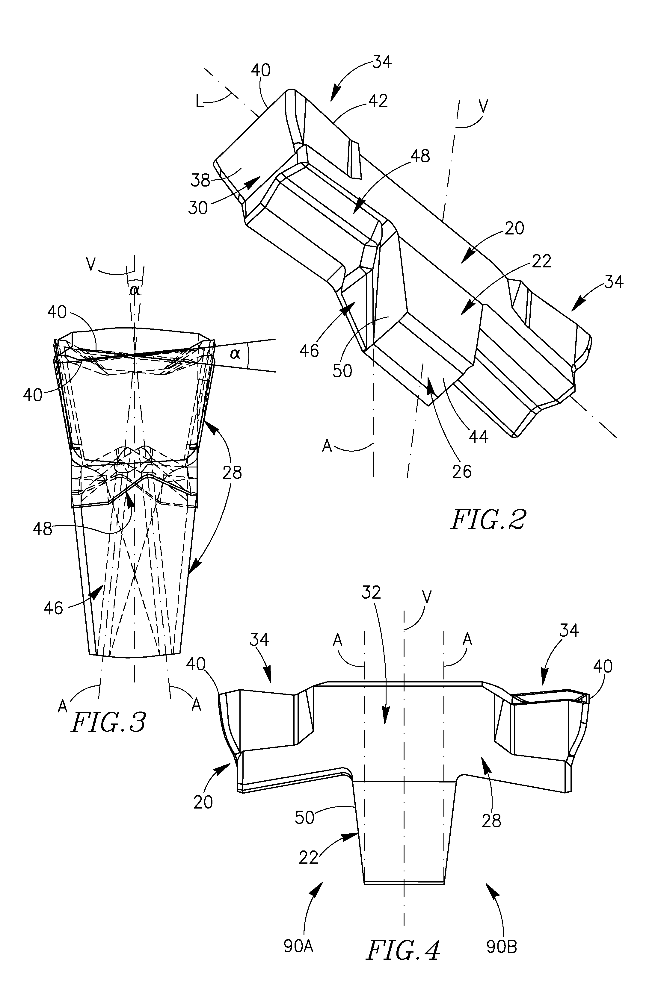
The present invention provides an indexable double-ended cutting insert with improved performance. The cutting insert has an insert symmetrical axis and is designed to be rotated in a plane perpendicular to the insert's upper surface. The cutting insert has a longitudinally extending body portion with a central portion and two insert cutting portions located at opposite ends of the body portion. The insert also has a holder with an insert pocket for securely holding the cutting insert. The cutting tool includes the insert holder with the cutting insert clamped therein. The technical effects of the invention include improved cutting performance, reduced wear and tear, and increased efficiency.

Problems solved by technology

No securing member adjacent the rake surface of the cutting insert is required to secure the cutting insert to the insert pocket, therefore chip formation during a cutting process goes undisturbed, on the other hand, the cutting insert has only one cutting portion.
The jaw which abuts the upper surface of the central body portion of the cutting insert may well disturb chip formation of chips cut from a workpiece by the front cutting edge of the cutting insert.

Method used


Image

  • Cutting tool and double-ended cutting insert therefor
  • Cutting tool and double-ended cutting insert therefor
  • Cutting tool and double-ended cutting insert therefor

Examples


Embodiment Construction

[0045]In the following description, various aspects of the present invention will be described. For purposes of explanation, specific configurations and details are set forth in order to provide a thorough understanding of the present invention. However, it will also be apparent to one skilled in the art that the present invention may be practiced without the specific details presented herein. Furthermore, well-known features may be omitted or simplified in order not to obscure the present invention.

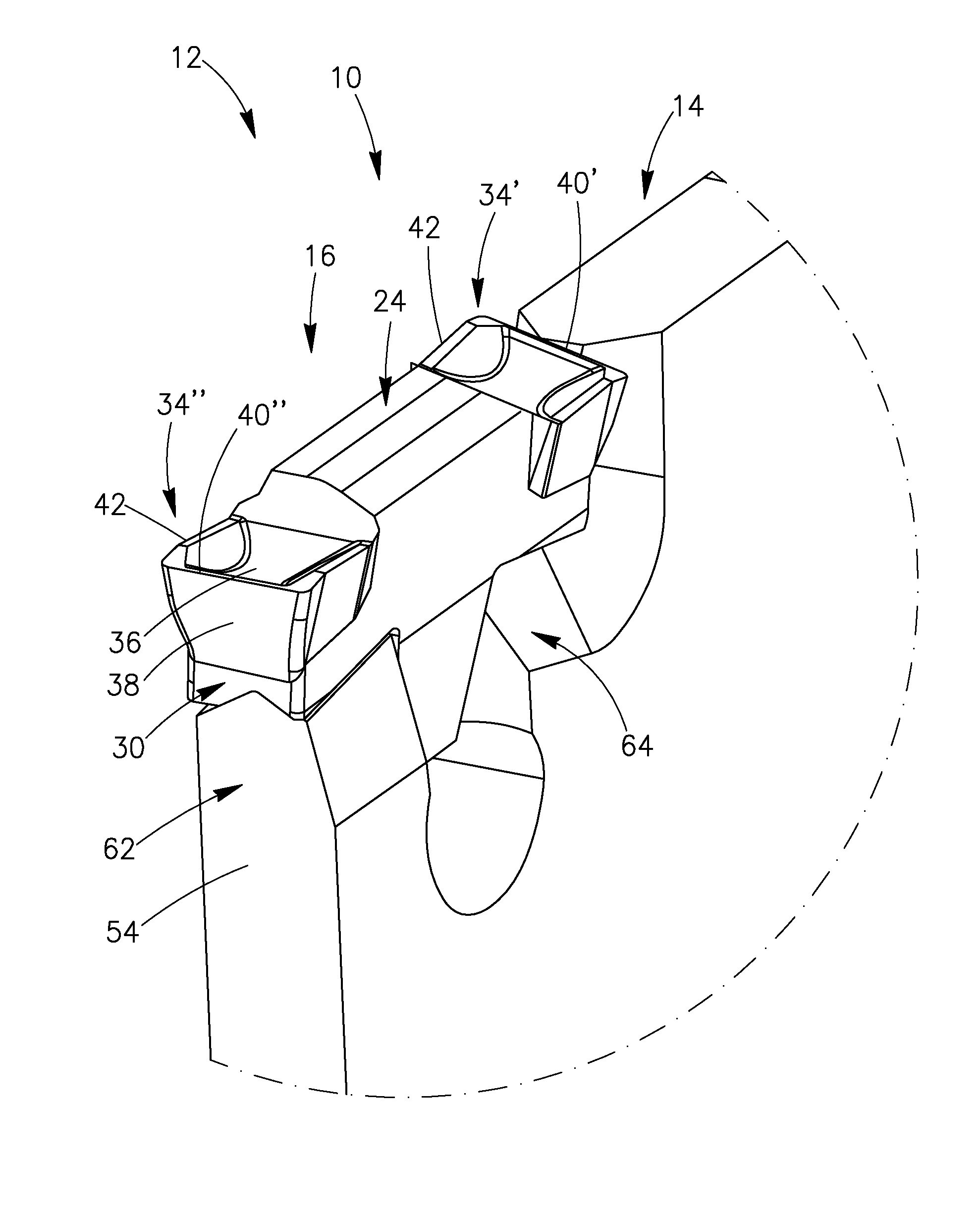
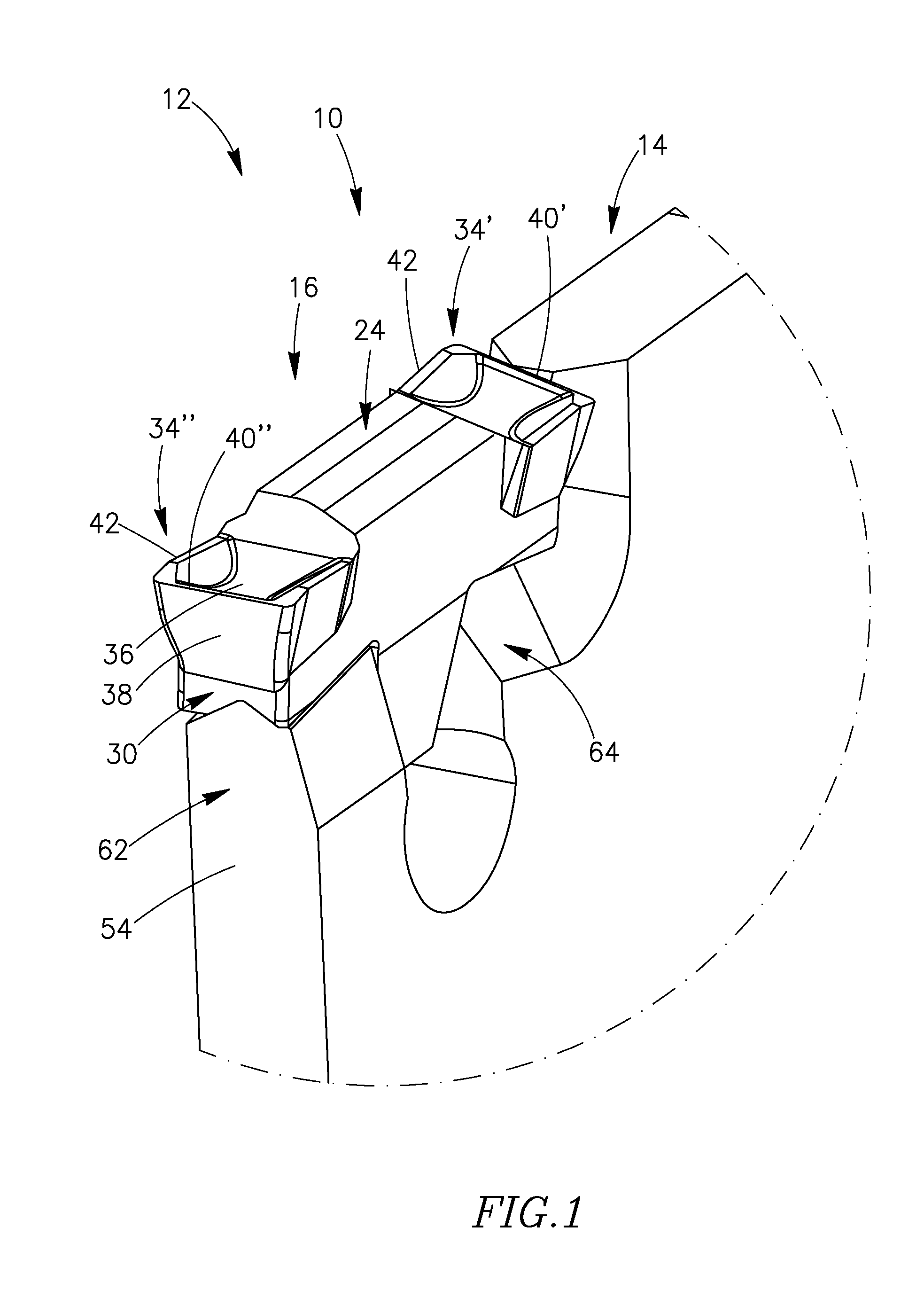
[0046]Reference is made to FIG. 1, showing an isometric view of an assembled tool cutting portion 10 of a cutting tool 12 in accordance with embodiments of the invention. The cutting tool 12 my have any required shape. The tool cutting portion 10 includes an insert holder 14 and an indexable double-ended cutting insert 16 releasably retainable in an insert pocket 18 on the insert holder 14. The insert holder 14 is typically made of metal, such as steel. The cutting insert 16 is typically...


PUM

PropertyMeasurementUnit
rotational symmetryaaaaaaaaaa
angleaaaaaaaaaa
acute angleaaaaaaaaaa

Abstract

A cutting tool for grooving, parting and turning machining operations is capable of grooving to unlimited depths of cut. The cutting tool includes an indexable double-ended cutting insert having a downwardly extending insert clamping portion resiliently clamped in a self-retaining manner in an insert pocket so that chip formation is not hindered during such machining operations.

Description

FIELD OF THE INVENTION[0001]The present invention relates to cutting tools for grooving, parting and turning machining operations capable of grooving to unlimited depths of cut.BACKGROUND OF THE INVENTION[0002]Such a cutting tool is disclosed, for example, in U.S. Pat. No. 7,163,361. A cutting insert is retained in an insert pocket of an insert holder via a forward upright V-shaped surface, an opposing flat rear surface and a V-shaped locating surface associated with the cutting portion. No securing member adjacent the rake surface of the cutting insert is required to secure the cutting insert to the insert pocket, therefore chip formation during a cutting process goes undisturbed, on the other hand, the cutting insert has only one cutting portion.[0003]U.S. Pat. No. 5,156,502 discloses a double-ended cutting insert having a cutting portion at each end. The cutting insert is designed so that the cutting tool has an unlimited depth of cut. The cutting insert is securely retained in t...

Claims


Application Information

Patent Timeline
Patent Type & Authority Patents(United States)
IPC IPC(8): B23B27/14B23B27/04
CPCB23B29/043B23B2200/161B23B2205/02B23B27/045Y10T407/25Y10T407/2284Y10T407/194Y10T407/2288Y10T407/235Y10T407/23Y10T407/2286B23B27/04B23B29/04
Inventor ATHAD, SHIMON
Owner ISCAR LTD
Learn More