
Photogrammetry system and method for determining relative motion between two bodies

a technology of relative motion and photogrammetry, which is applied in the field of photogrammetry utilized to determine the relative position of two bodies, can solve the problems of not allowing the use of fish-eye or hyperbolic lenses in cameras

Active Publication Date: 2014-02-18
NASA
View PDF11 Cites 38 Cited by
  • Summary
  • Abstract
  • Description
  • Claims
  • Application Information

AI Technical Summary

Problems solved by technology

However, many objects commonly measured do not naturally exhibit such features.
Existing photogrammetry systems may require specific types of camera lenses, and may not permit use of cameras having fish-eye or hyperbolic lenses.

Method used


Image

  • Photogrammetry system and method for determining relative motion between two bodies
  • Photogrammetry system and method for determining relative motion between two bodies
  • Photogrammetry system and method for determining relative motion between two bodies

Examples


Embodiment Construction

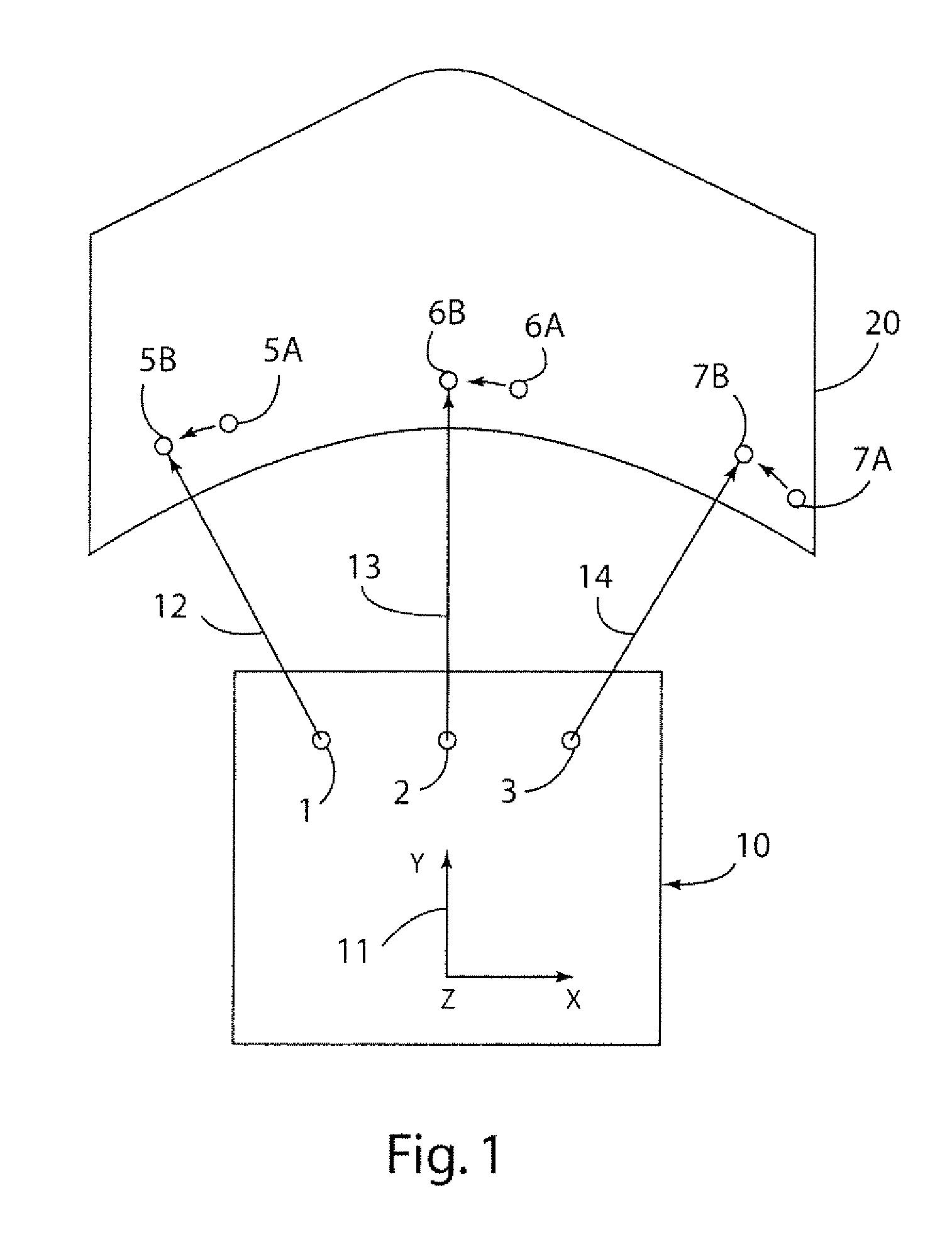
[0021]For purposes of description herein, the terms “upper,”“lower,”“right,”“left,”“rear,”“front,”“vertical,”“horizontal,” and derivatives thereof shall relate to the invention as oriented in FIG. 1. However, it is to be understood that the invention may assume various alternative orientations, except where expressly specified to the contrary. It is also to be understood that the specific devices and processes illustrated in the attached drawings, and described in the following specification are simply exemplary embodiments of the inventive concepts defined in the appended claims. Hence, specific dimensions and other physical characteristics relating to the embodiments disclosed herein are not to be considered as limiting, unless the claims expressly state otherwise.

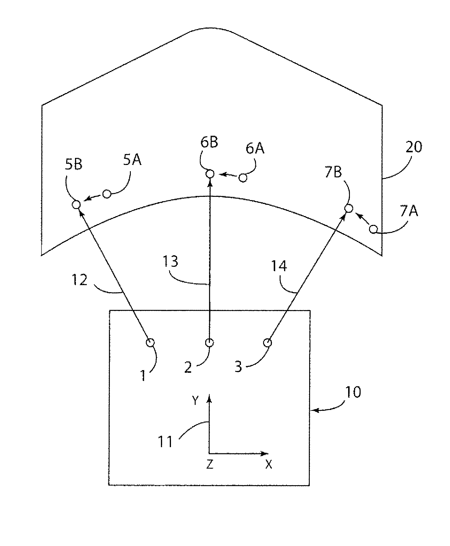
[0022]Referring to FIG. 1, a system utilizing the present invention includes first and second bodies 10 and 20. In general, the bodies 10 and 20 may comprise various types of rigid or semi-rigid bodies capable of holding...


PUM


Abstract

A photogrammetry system and method provide for determining the relative position between two objects. The system utilizes one or more imaging devices, such as high speed cameras, that are mounted on a first body, and three or more photogrammetry targets of a known location on a second body. The system and method can be utilized with cameras having fish-eye, hyperbolic, omnidirectional, or other lenses. The system and method do not require overlapping fields-of-view if two or more cameras are utilized. The system and method derive relative orientation by equally weighting information from an arbitrary number of heterogeneous cameras, all with non-overlapping fields-of-view. Furthermore, the system can make the measurements with arbitrary wide-angle lenses on the cameras.

Description

STATEMENT REGARDING FEDERALLY SPONSORED RESEARCH OR DEVELOPMENT[0001]The invention described herein was made by employees of the United States Government, and may be manufactured and used by or for the Government of the United States of America for governmental purposes without the payment of any royalties thereon or therefor.BACKGROUND OF THE INVENTION[0002]1. Field of the Invention[0003]The present application is related to photogrammetry utilized to determine the relative position of two bodies.[0004]2. Description of the Related Art[0005]Photogrammetry is the science of making measurements from photographs. In general, the output of photogrammetry is typically a map, a drawing, or a three-dimensional (3D) model of a real-world object or scene. Photographic images are the result of a perspective projection of a 3D object onto two dimensions. Consequently, one or more photographic images can be reverse-engineered to derive the 3D shape of the original object. The solution provides...

Claims


Application Information

Patent Timeline
Patent Type & Authority Patents(United States)
IPC IPC(8): G06T15/00G06K9/00G01B11/26G06T5/00G01B5/004
CPCG06T2207/30204G01C11/04G06T7/004G06T7/0018G06T7/70G06T7/80
Inventor MILLER, SAMUEL ASEVERANCE, KURT
Owner NASA
Learn More