Surgical nail

a nail and surgical technology, applied in the field of surgical nails, can solve the problems of difficult to accurately determine the position of the locking hole in the nail, and fractures may be difficult to trea

Active Publication Date: 2014-03-04
DEPUY SYNTHES PROD INC
View PDF61 Cites 76 Cited by
  • Summary
  • Abstract
  • Description
  • Claims
  • Application Information

AI Technical Summary

Benefits of technology

[0004]The present invention relates to a surgical nail that allows a user to verify an alignment of guide bores of a distal aiming arm attached to a distal end of a surgical nail upon insertion of the surgical nail into a bone and to correct the alignment if necessary.

Problems solved by technology

Due to the critical structures surrounding the clavicle, the thin medullary canal and the limited bone stock of the clavicle, these fractures may be difficult to treat.
In some cases, however, it may be difficult to accurately determine the position of a locking hole in a nail.

Method used


Image

  • Surgical nail
  • Surgical nail
  • Surgical nail

Examples


first embodiment

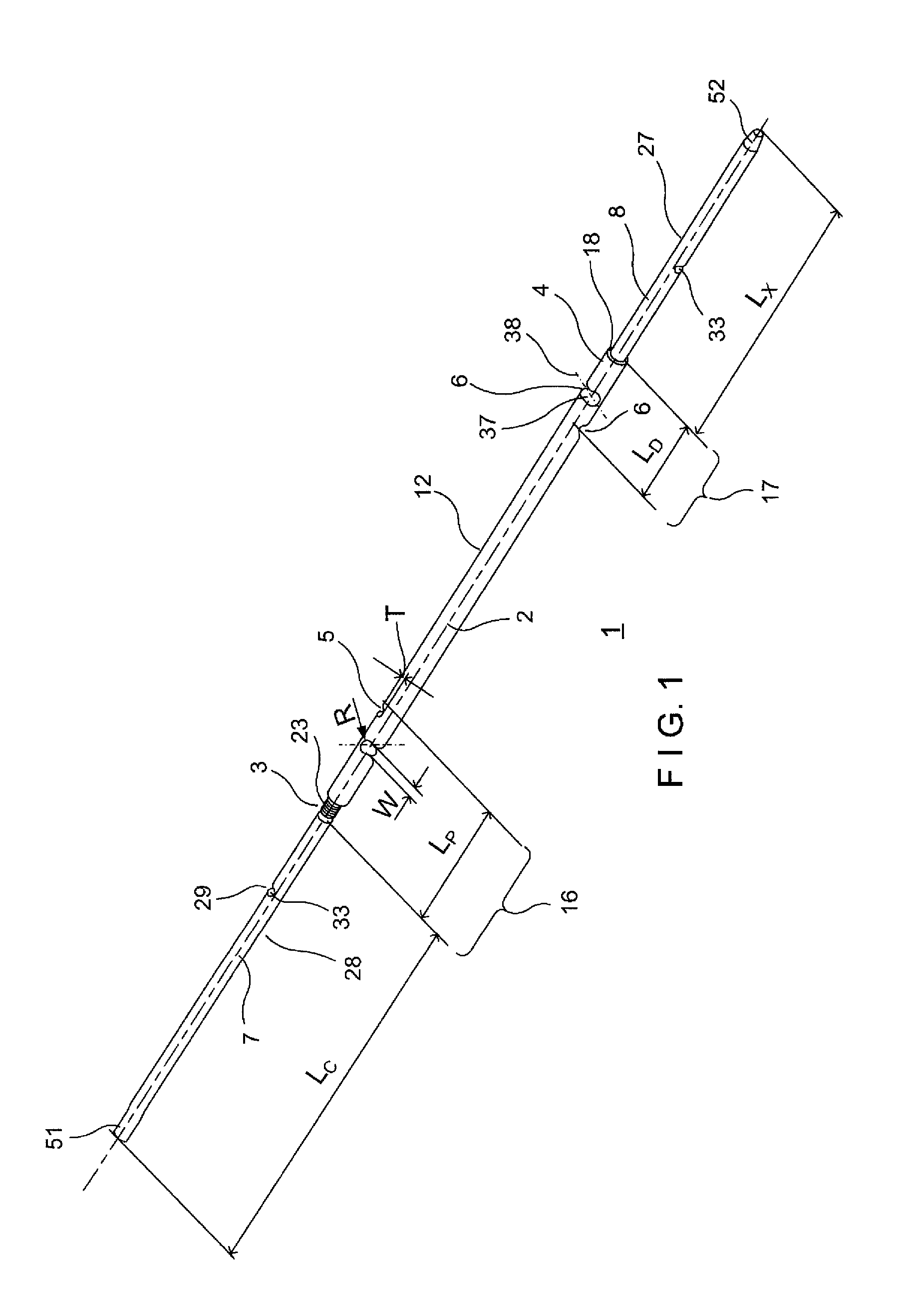
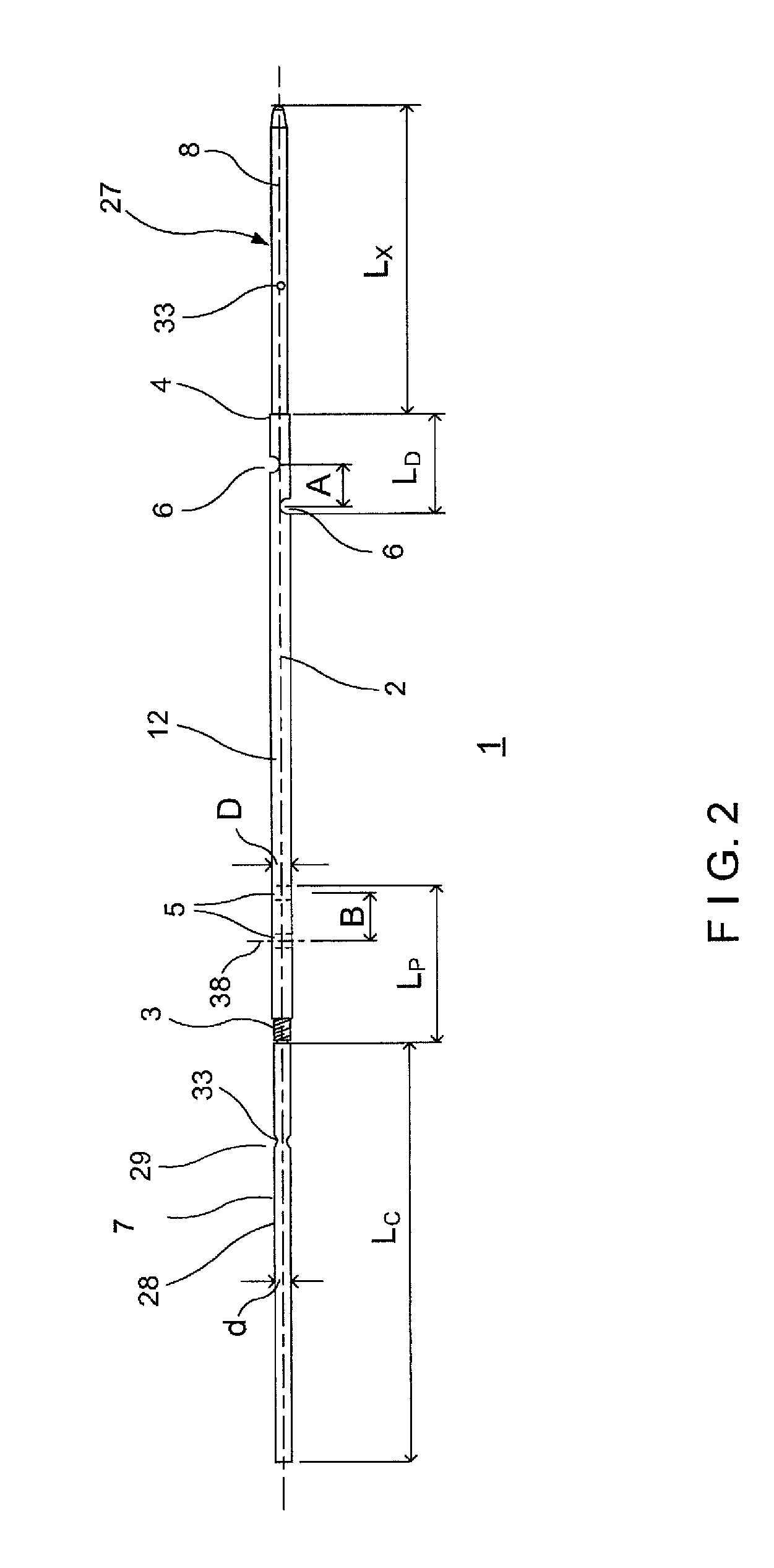
[0107]As shown in FIGS. 1-22, a system and method according to the present invention comprises a clavicle nail 1 sized and shaped for insertion into a clavicle 9 to fix a fracture thereof. The nail 1 may be inserted into the clavicle 9 using a handle 15 and fixed therein by inserting bone fixation elements such as locking screws 24 through the clavicle 9 and into proximal and distal locking apertures 5, 6 of the nail 1. The system may further comprise proximal and distal aiming devices 13, 14, as shown in FIG. 27, which may be attached to the nail 1, for aligning a drill and / or the bone fixation elements with corresponding ones of the proximal and distal locking apertures 5, 6. In a further embodiment, the system may further comprise a reamer 30, as shown in FIGS. 28-32, for drilling a hole 32 through the clavicle 9 within which the nail 1 is to be accommodated.

[0108]As shown in FIGS. 1-3, the nail 1 includes a nail body 12 extending along a longitudinal axis 2 from a proximal end 3...

second embodiment

[0118]FIGS. 35 and 36 show a nail 1a of the present invention. The nail 1a may be substantially similar to the nail 1, as described, above, comprising a nail body 12a along with a distal connecting element 27a and a proximal connecting element 28a. The distal and proximal connecting elements 27a, 28a may be formed as, for example, rod-shaped distal and proximal portions 8a, 7a, respectively. It should be noted that different parts have been numbered accordingly.

[0119]In the nail 1a, the distal connecting element 27a and the proximal connecting element 28a are removably coupled to the nail body 12a. The removably coupled distal and proximal connecting elements 27a, 28a are press-fitted into openings 100, 101 formed in the distal and proximal ends 4a, 3a, respectively. The press-fit connection between the connecting elements 27a, 28a and their respective ends 4a, 3a holds these parts together by friction so that inadvertent or unexpected removal is prevented.

[0120]FIG. 35 shows the pr...

sixth embodiment

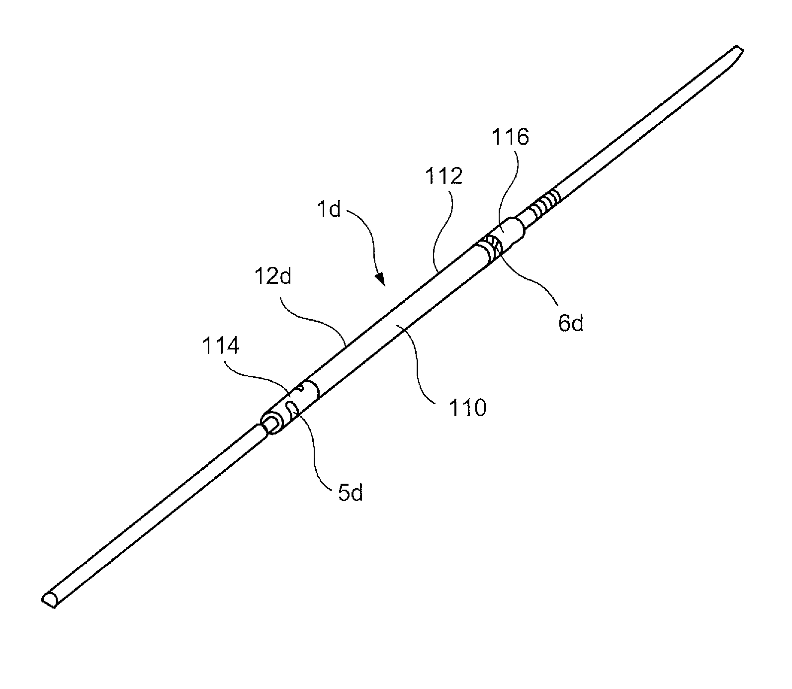
[0133]FIGS. 50 and 51 show a nail 1e of the present invention. The nail 1e may be substantially similar to the nail 1, as described above, comprising a nail body 12e along with a distal connecting element 8e extending from a distal end 4e thereof. The distal connecting element 8e may be formed as, for example, rod-shaped distal end portions. It should be noted that different parts have been numbered accordingly.

[0134]In the sixth embodiment, the proximal end features a proximal end locking aperture 5e and has no proximal connecting element. The proximal locking aperture 5e may extend from a proximal end 3e of the nail body 12e through a wall of the nail body 12e such that the an axis of the proximal locking aperture 5e is arranged at an angle relative to the longitudinal axis of the nail 1e. Thus, a bone fixation element may be inserted through the proximal end 3e to fix the nail body 12e to the bone and a proximal aiming guide is not required to guide the bone fixation element thro...


PUM


Abstract

A surgical nail for treating a fractured bone includes a nail body extending along a longitudinal axis from a trailing end to a leading end and including a trailing end locking aperture extending transversely through a trailing end portion thereof and a leading end locking aperture extending transversely through a leading end portion thereof; a trailing end connecting element located at the trailing end of the nail body adapted and configured to be coupled to a trailing end aiming guide; and a leading end connecting element at the leading end of the nail body adapted and configured to be coupled to a leading end aiming guide.

Description

PRIORITY CLAIM[0001]This application claims priority to U.S. Provisional Application Ser. No. 61 / 381,264 filed on Sep. 9, 2010 and entitled “Surgical Nail,” U.S. Provisional Application Ser. No. 61 / 476,597 filed on Apr. 18, 2011 and entitled “Locking Clavicle Nail” and U.S. Provisional Application Ser. No. 61 / 498,892 filed on Jun. 20, 2011 and entitled “Surgical Nail” and U.S. Provisional Application Ser. No. 61 / 500,297 filed on Jun. 23, 2011 and entitled “Clavicle Nail with Lateral Expanding and Actuated Portion,” the entire disclosures of which are incorporated herein by reference.FIELD OF THE INVENTION[0002]The present invention generally relates to a surgical nail and, in particular, to a clavicle nail comprising proximal and distal connecting elements for coupling an aiming guide to a nail body.BACKGROUND[0003]Clavicle (e.g., collarbone) fractures account for 5 to 7% of adult fractures of which 80 to 85% are in the mid third of the clavicle. Due to the critical structures surro...

Claims


Application Information

Patent Timeline
Patent Type & Authority Patents(United States)
IPC IPC(8): A61F2/30A61B17/58A61B17/56
CPCA61B17/7208A61B17/7283A61B2017/0046A61B17/72A61B17/725A61B17/1725A61B17/7291A61B17/7225A61B17/164A61B17/1739A61B17/86A61B17/17A61B17/88
Inventor OVERES, TOMWALTER, BRUNOJAEGER, MARTINANDERMATT, DANIEL
Owner DEPUY SYNTHES PROD INC
Why Eureka
Try Eureka