Plastic preforms with marking for position detection

a technology of position detection and plastic preforms, applied in the field of plastic preforms, can solve problems such as performance impairment, and achieve the effect of simplifying the blowability of the subsequent moulding process

Active Publication Date: 2014-03-04
KRONES AG
View PDF18 Cites 4 Cited by
  • Summary
  • Abstract
  • Description
  • Claims
  • Application Information

AI Technical Summary

Benefits of technology

[0023]In this way, a “machine-readable” plastic preform can be made available. In this connection, the treatment machine can classify the plastic preform by means of this code (in particular applied to the carrier ring) and can react on the plastic preform, if required. Thus, the machine can initiate suitable measures, such as e.g. discharge of the plastic preform, adaptation of processing parameters, orientation of the plastic preform and the like.
[0024]In another advantageous embodiment, the annular body encloses the plastic preform completely and is formed without continuous recesses in the longitudinal direction of the plastic preform. As mentioned above, the blowability in a subsequent moulding process is simplified in this way.

Problems solved by technology

This in turn results in impaired performances.

Method used


Image

  • Plastic preforms with marking for position detection
  • Plastic preforms with marking for position detection
  • Plastic preforms with marking for position detection

Examples


Embodiment Construction

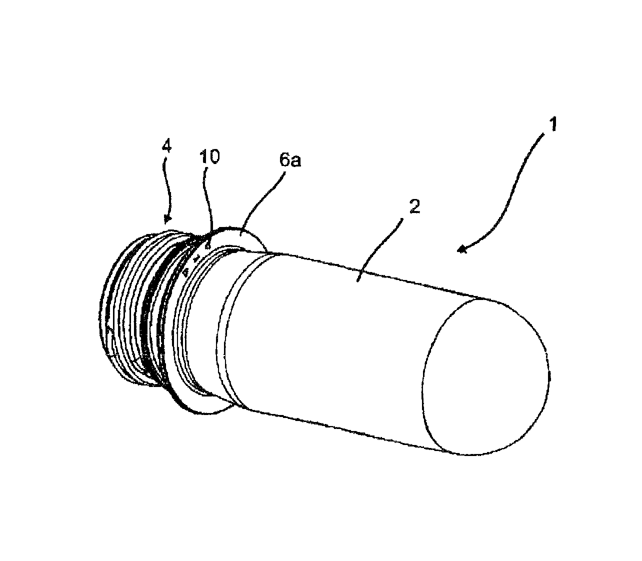
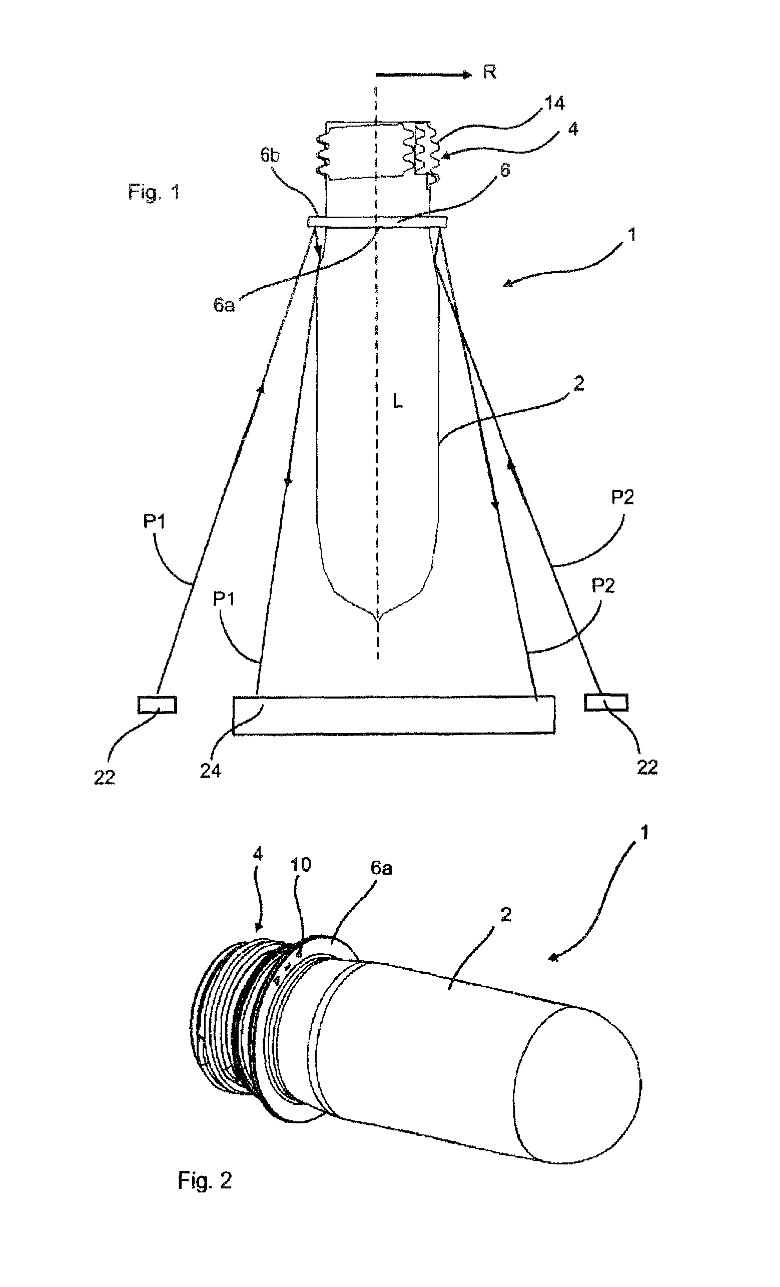
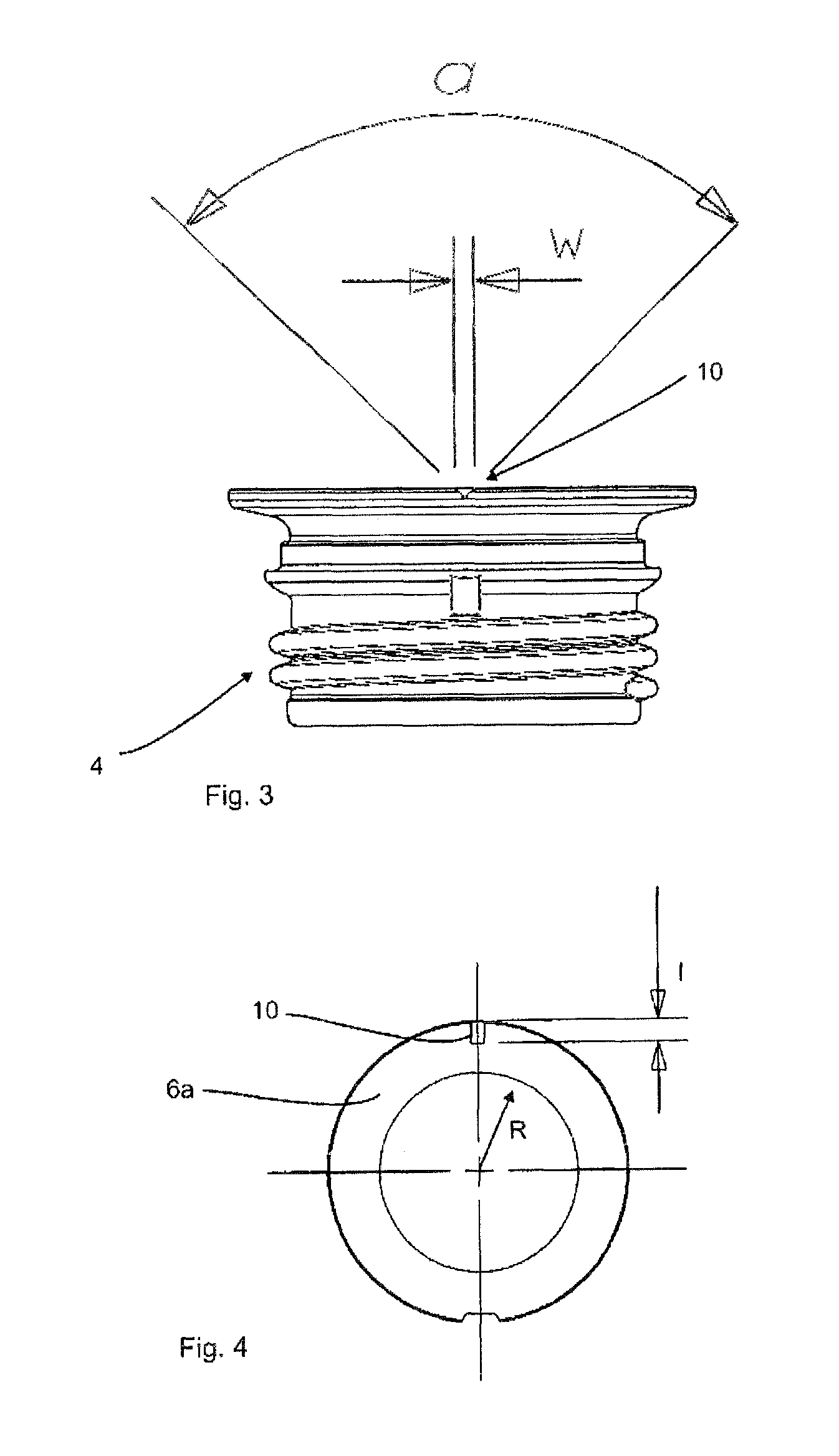
[0036]FIG. 1 shows a side view of a plastic preform 1 according to the invention. Here, this plastic preform has a base body 2, this base body being expandable in the course of an expansion process, and a thread region 4 which in this case is formed in one piece with the base body 2. The thread region 4 is not stretched in the course of the expansion process. The reference numeral 14 relates to a thread turn of the thread of the plastic preform. Furthermore, the plastic preform has an annular body, i.e. a carrier ring 6 which in turn has a surface 6b facing up, i.e. facing the thread region 4, and a surface 6a facing down, i.e. facing the base body 2.

[0037]In an inspection of plastic preforms made from clear, at least partially translucent material, the major proportion of the light passes through the translucent carrier ring 6. This proportion causes disturbances in the room, at the thread or at the holding device which are well optically perceivable through a polished carrier ring...


PUM

PropertyMeasurementUnit
lengthaaaaaaaaaa
lengthaaaaaaaaaa
lengthaaaaaaaaaa

Abstract

A plastic preform, having a base body, a thread region arranged on the base body, wherein the thread region is formed in one piece with the base body, and a ring-shaped section which is arranged underneath the thread region, which extends outwards in a radial direction (R) of the plastic container and which is formed in one piece with the base body, wherein the ring-shaped section has a first surface facing the base body and a second surface facing the thread region. At least one optically perceivable marking is arranged on the surface facing the base body.

Description

BACKGROUND OF THE INVENTION[0001]The present invention relates to a plastic preform. Such plastic preforms have been known for a long time from the prior art and e.g. serve to be moulded to become plastic containers (e.g. beverage bottles) in the course of blow moulding processes, in particular stretch-blow moulding processes. In the process, the heated plastic preform is usually moulded to a container by means of a stretch-blow moulding machine. In this connection, also known from the prior art are containers which are shaped such that they are not rotation-symmetrical but have an oval cross-section, for example. Additionally, containers exist wherein the lid has to be orientated so it is fitted in the correct position with regard to the bottle body which may be required because of the container design or also because of technical conditions.[0002]This orientation is usually achieved by means of cams or notches in the region of the mouthpiece of the plastic preform which can be ali...

Claims


Application Information

Patent Timeline
Patent Type & Authority Patents(United States)
IPC IPC(8): B32B1/02B32B1/00
CPCB29B2911/14466B29B2911/14793B29B2911/14553B29B2911/14106B29B2911/1404B29B2911/14133B29C49/06B29B2911/14026B29B11/14B29B2911/1402B29K2105/258B29B2911/14033B29B2911/1444B29B2911/14506B29B2911/14726B29B2911/14333B29C2949/3024B29C2949/26B29C2949/28B29C2949/24B29C2949/22B29C2949/3032B29C2949/073B29C2949/079B29C2949/0777B29C2949/0773B29C2949/0797B29C2949/0831B29C2949/0841B29C49/071B29C2949/0715Y10T428/1397Y10T428/1379Y10T428/1352
Inventor KWIRANDT, RAINERHUETTNER, GERALD
Owner KRONES AG
Why Eureka
Try Eureka