Three-dimensional modeling of the oral cavity

a three-dimensional modeling and oral cavity technology, applied in the field of computerized modeling of three-dimensional objects, can solve the problems of inability to recognize surficial surgical features on intra-oral objects, inability to achieve surface detail in many situations, and inability to achieve surface detail in dental work, etc., to achieve the effect of facilitating 3d intra-oral modeling

Active Publication Date: 2014-03-04
DENSYS
View PDF6 Cites 9 Cited by
  • Summary
  • Abstract
  • Description
  • Claims
  • Application Information

AI Technical Summary

Benefits of technology

[0023]It is a goal of the present invention to facilitate 3D intra-oral modeling for dental applications while requiring minimal apparatus to be placed inside the mouth.
[0025]It is a further goal of the present invention to minimize or eliminate the effect of movement of the patient, the practitioner, and the apparatus during the procedure of 3D intra-oral imaging for dental applications. To attain these goals, the present invention utilizes a single camera (or “visual sensor”) to produce an image of an intra-oral scene, such that the image contains 3D information about the surface of the intra-oral features to be modeled.

Problems solved by technology

Important constraints in applying medical optical imaging to the dental field include:space limitations—equipment must be compact enough to fit comfortably within the confines of the mouth;time limitations—the image must be formed in a brief time to avoid problems of the movement of the patient as well as the movement of the practitioner and apparatus; andsurface detail limitations—accurately plotting 3 surface contours of intra-oral scenes must take into account the absence or paucity of surface detail in many close-up applications, where only partial views of intra-oral features may be available.
In practice, a limitation is imposed by the lack of recognizable surficial surgical features on intra-oral objects.
This limitation is often encountered in situations in which a surface is to be sampled three dimensionally for 3D modeling.
As previously noted, however, a significant limitation in dental work is the lack of surface detail in many situations.
Without a substantial amount of surface detail, it is not possible to unambiguously match surface features for accurate triangulation.
Unfortunately, however, scanning (which is essentially a one-dimensional, or “1D” approach) can sometimes require excessive time, particularly if high resolution is desired.
Corby, however, is limited to the use of a one-dimensional scanning methodology, which (as discussed above) may not be suitable for certain dental applications because of the patient / practitioner movement that is likely to be encountered.
A limitation associated with the employment of regular grids is that of discontinuities and ambiguities.
Broken grid lines are a cause for errors because of the ambiguities introduced by this phenomenon.
One of the recognized problems in using structured light in lines or points is that of aliasing, or false matching of the structured illumination.
A plain point of light is normally indistinguishable from other plain points of light, and so there can arise ambiguities in matching the same point from one image to another.
If two different points are mistakenly matched when triangulating different images, the resulting z-axis calculation will be in error, and the 3D model will be defective.
(The same problem applies to the use of lines.)
However, this cannot be employed for projected (non-scanned) images or for stored images where features are matched after the structured illumination has been projected, because there is no timing information.
It also cannot be used with the single imaging method mentioned above.
In particular, certain prior art schemes would require illuminating the same areas of the intra-oral scene with patterns over a prolonged time period or repeatedly at different times. These practices, however, can introduce inaccuracies in the measurements due to any relative movement between the dental patient, the apparatus that projects the illumination, and the apparatus that captures the images (camera).
A principal limitation of Albeck '151 is that the random patterns, being created by a physical process (laser speckle), can be neither stored nor reproduced.
As noted above, an important limitation is imposed by the small space inside the mouth, which does not permit the introduction of bulky apparatus.

Method used


Image

  • Three-dimensional modeling of the oral cavity
  • Three-dimensional modeling of the oral cavity
  • Three-dimensional modeling of the oral cavity

Examples


Embodiment Construction

[0060]The principles and operation of a method according to the present invention may be understood with reference to the drawings and the accompanying description.

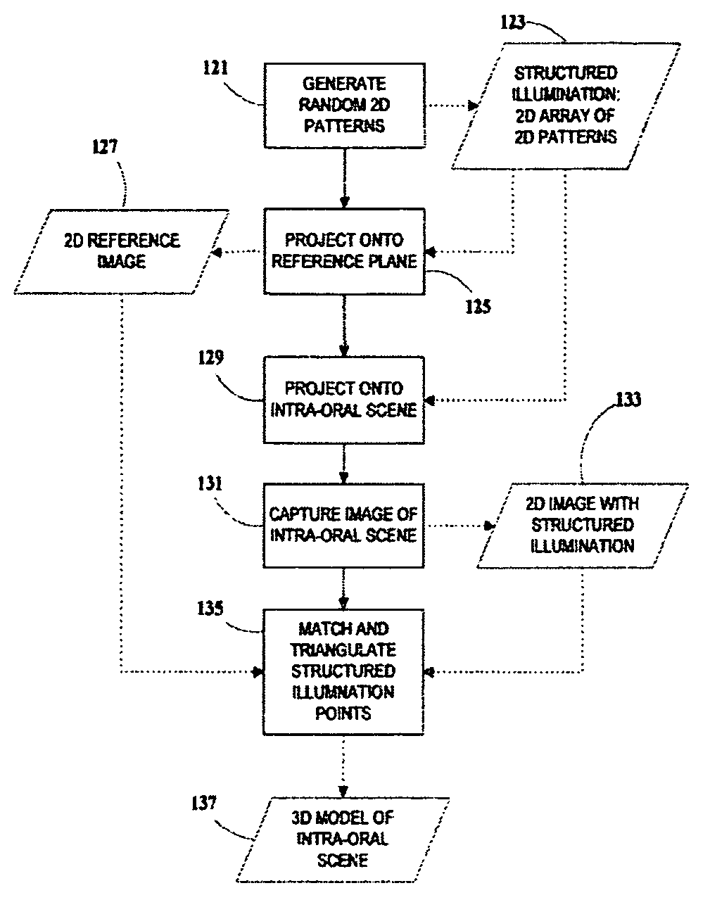
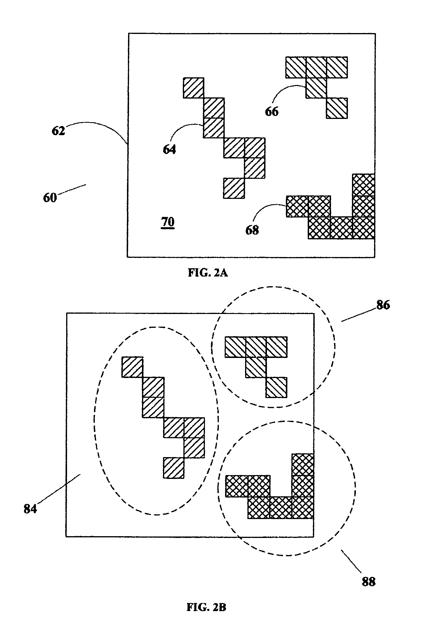
[0061]In accordance with the present invention, structured illumination containing stored random patterns is used to convey surficial features to an intra-oral scene to be modeled in three dimensions by a single image, wherein triangulation is performed relative to a stored image of the structured illumination impinging from a different angle on a known surface, such as a plane. The method of the invention can be applied in various dental applications and fields, as well as be put to use in dental veterinary practice, and forensic dental medicine. In a preferred embodiment of the present invention, the light projected on the site of interest within the mouth bears randomly-structured and randomly-distributed patterns such that each projected pattern is probabilistically unique over the entire area onto which the light has...


PUM


Abstract

A method for creating three-dimensional models of intra-oral scenes features. The intra-oral scene is illuminated by a two-dimensional array of structured illumination points, with anti-aliasing achieved by using stored two-dimensional patterns of pixels for anti-aliasing. Using a single camera to form images reduces the amount of apparatus necessary to introduce into the patient's mouth. Three-dimensional models are obtained from the single image by triangulation with a stored image of the structured illumination onto a reference surface such as a plane. Alternative methods include the use of “bar-coded” one-dimensional patterns.

Description

FIELD OF THE INVENTION[0001]The present invention relates to computerized modeling of three-dimensional objects, and, more particularly, to a system and method for three-dimensional modeling of intra-oral objects and features in dental applications.BACKGROUND OF THE INVENTION[0002]There is a need in dental medicine for making three dimensional (herein also denoted as “3D”) models of internal scenes of the mouth. The term “intra-oral scene” herein denotes any collection of intra-oral objects, artifacts, surfaces, or features which can be visualized and modeled. Such models of intra-oral scenes can support various aspects of dental practice. A well-known illustration of the utility, effectiveness, and procedural and economic impact of automatic measuring and imaging techniques in dentistry involves the examination, charting, diagnosing, and treatment of dental patients who require prostheses such as crowns, bridges, dentures, or implants. Data and information obtained from measuring, ...

Claims


Application Information

Patent Timeline
Patent Type & Authority Patents(United States)
IPC IPC(8): G06T15/00
CPCA61C9/006A61C13/0004G16H20/40
Inventor ERNST, MAURICE MOSHEGEFFEN, MICHANETA, URICOHEN, CARMI
Owner DENSYS
Why Eureka
Try Eureka