Ball handle assembly for a handheld tool

a technology for hand-held tools and handles, which is applied in the field of hand-held tools, can solve the problems of handiness, insufficient adjustment of second-hand handles for all body types/sizes,

Active Publication Date: 2014-03-11
MTD PRODUCTS
View PDF103 Cites 14 Cited by
  • Summary
  • Abstract
  • Description
  • Claims
  • Application Information

AI Technical Summary

Problems solved by technology

Additionally, each user's body shape varies, and these secondary handles do not adequately adjust for all body types / sizes, handedness, or for the type of implement attached to the boom.

Method used


Image

  • Ball handle assembly for a handheld tool
  • Ball handle assembly for a handheld tool
  • Ball handle assembly for a handheld tool

Examples


Embodiment Construction

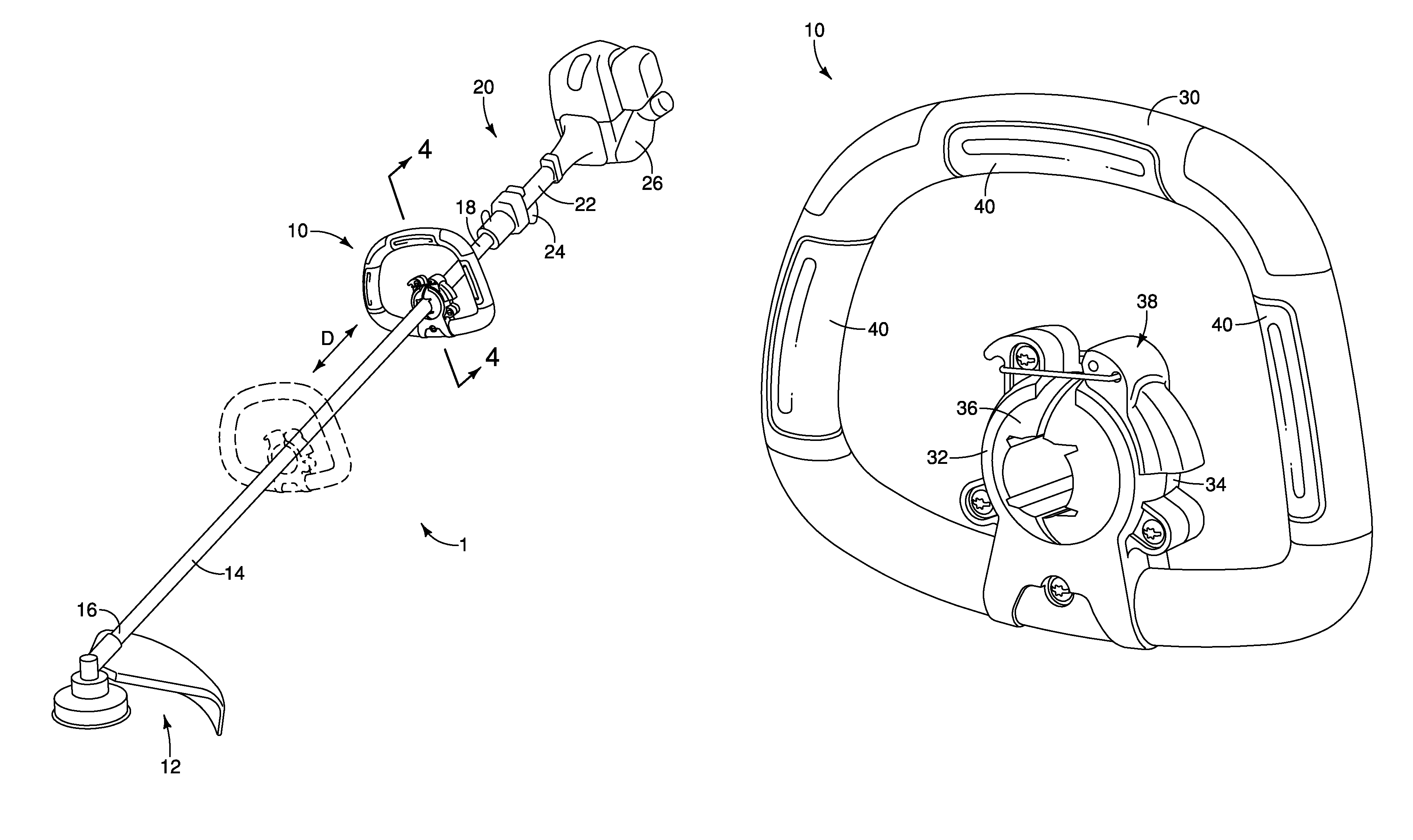
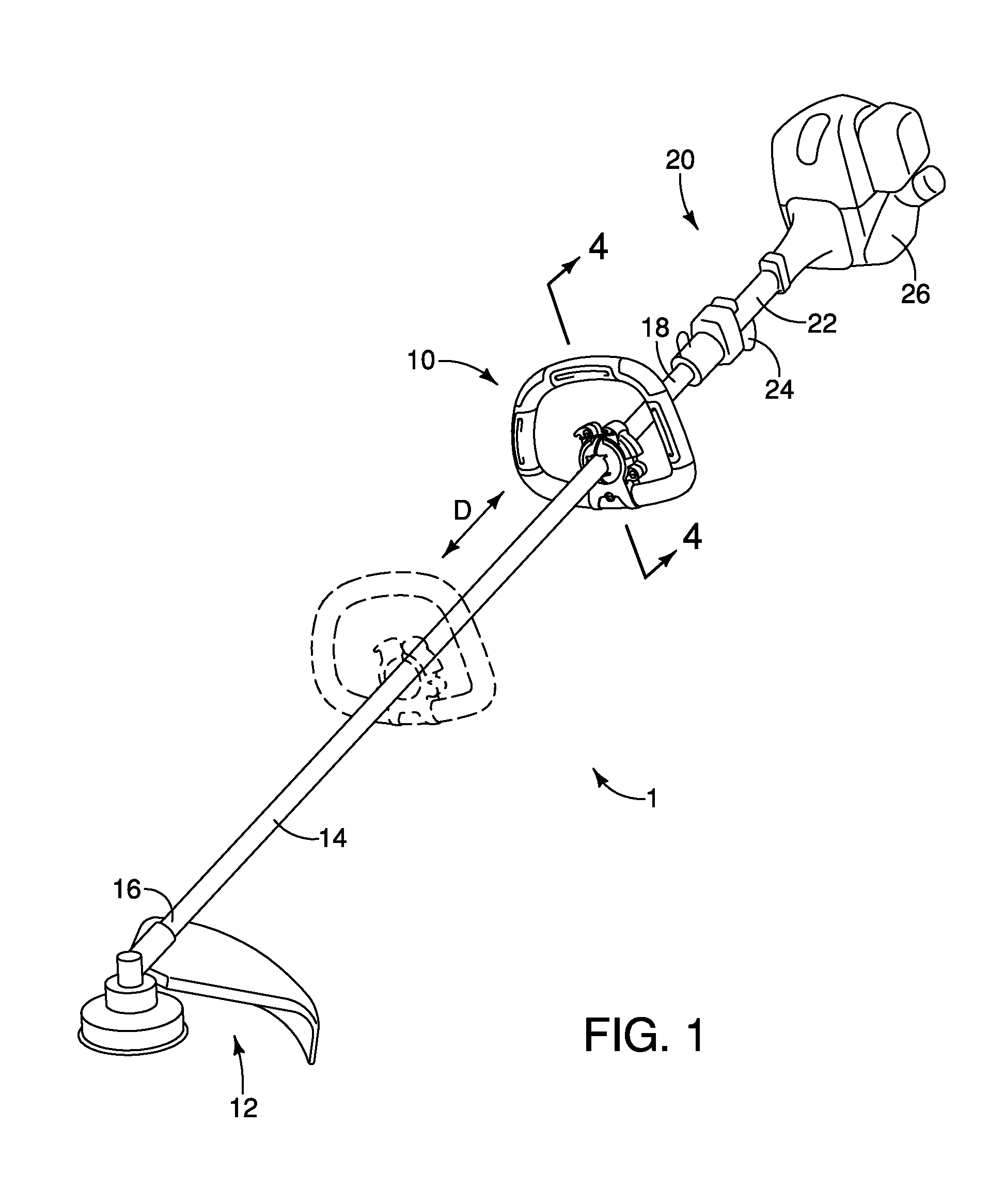
[0020]Regarding FIG. 1, an exemplary embodiment of a handheld tool 1 with a ball handle assembly 10 operatively connected thereto is provided. In the illustrated embodiment, the handheld tool 1 includes a powered mechanism 12 which is shown as a trimmer, but it should be understood by one of ordinary skill in the art that any type of powered mechanism 12 can be attached to an elongated boom 14 of the handheld tool 1 including, but not limited to, a string trimmer, a hedge trimmer, pole saw, blower, or the like. The ball handle assembly 10 is configured to be operatively attached to the boom 14 that that has a first distal end 16 and a second distal end 18. The ball handle assembly is movable in four distinct manners relative to said boom 14 to provide an operator with increased ergonomic control of the handheld tool 1.

[0021]As shown in FIG. 1, the exemplary embodiment of the ball handle assembly 10 is attached to a boom 14. The boom 14 is illustrated as being a generally hollow, cyl...


PUM


Abstract

A ball handle assembly for a handheld tool is provided. The handheld tool includes a powered mechanism, an actuating mechanism for actuating the powered mechanism, and an elongated boom extending between the powered mechanism and the actuating mechanism. A ball handle assembly is adjustably attached to the boom to allow a user to adjust the ball handle assembly relative to the boom to provide a comfortable and ergonomic orientation regardless of the handedness of the operator. The ball handle assembly is translatable along the length of the boom, and the ball handle assembly provides for three degrees of rotation relative to the boom.

Description

FIELD OF THE INVENTION[0001]The present invention is directed to a lawn and garden handheld tool, and more particularly, to the handle for a handheld tool.BACKGROUND OF THE INVENTION[0002]Handheld lawn and garden tools such as string trimmers, pole saws, and the like having an elongated boom with a tool or implement disposed on one distal end and a control mechanism disposed on the opposing distal end are well known in the art. These handheld tools typically include a primary handle at a distal end of the elongated boom with a trigger or other actuating mechanism integrated with the primary handle. Because of the weight of the implement being attached to the opposing distal end, a secondary handle is usually attached to the boom at a location between the primary handle and the implement. The secondary handles often are either fixed relative to the boom or they are rotatable about the central axis of the boom and / or are slideable along the length of the boom.[0003]Users of these elon...

Claims


Application Information

Patent Timeline
Patent Type & Authority Patents(United States)
IPC IPC(8): B25G1/00A01D34/90A01D34/00A01G3/06
CPCA01D34/902B25F5/026A01D34/416
Inventor VIERCK, BENJAMIN, EDWIN
Owner MTD PRODUCTS
Why Eureka
Try Eureka