Image capture unit in a surgical instrument

a surgical instrument and image capture technology, applied in the field of endoscopic imaging, can solve the problems of lateral color distortion, uneven performance of left and right image sensors, and difficulty in high-quality stereoscopic images in small outer diameter distal-end image capture systems, and achieve the effect of eliminating the need for lens calibration

Active Publication Date: 2014-03-18
INTUITIVE SURGICAL OPERATIONS INC
View PDF16 Cites 32 Cited by
  • Summary
  • Abstract
  • Description
  • Claims
  • Application Information

AI Technical Summary

Benefits of technology

[0015]An image capture unit with coplanar image capture sensors overcomes shortcomings of the prior art cameras used in the distal end of an endoscope and provides many new capabilities. Each of the coplanar image capture sensors in a channel of the endoscope has a common front end optical structure, e.g., the lens assembly in the image capture unit is the same for each of the sensors. The common optical and coplanar configuration of the image capture sensors eliminates the need for calibration of lens artifacts. Re-registration of different images captured in independent channels of the endoscope is not required. The images captured in a channel of the endoscope are temporally registered. The images are also spatially registered relative to each other.
[0016]Visible images of a scene or a visible image of a scene and one or more fluorescence images in the scene are acquired by the image capture unit. A controller enhances the acquired images. The enhanced images are displayed on a stereoscopic display, in one aspect. The enhanced images may include (a) visible images with enhanced feature definition, in which a particular feature in the scene is emphasized to the operator of a minimally invasive surgical system, for example; (b) images having increased image apparent resolution; (c) images having increased dynamic range; (d) images displayed in a way based on a pixel color component vector having three or more color components; and (e) images having extended depth of field.
[0026]For enhanced feature differentiation, the light received from the lens assembly enters the prism assembly through a distal face. The beam splitter is configured to reflect a first portion of the received light on a basis of a polarization state of the received light, and to transmit a second portion of the received light on the basis of the polarization state of the received light. A first optical path length from the distal face to the first sensor surface is about equal to a second optical path length from the distal face to the second sensor surface. A controller is coupled to the first and second image capture sensors. The controller combines information from a first image captured by the first image capture sensor and information from a second image captured by the second image capture sensor to generate an image increasing the saliency of a feature in the image based on polarization differences in the received light.
[0028]In one aspect, the first and second image capture sensors are color image capture sensors. Again, the controller is coupled to the first and second image capture sensors. The controller combines information from a first image captured by the first image capture sensor and information from a second image captured by the second image capture sensor to generate an image having one of enhanced spatial resolution and enhanced dynamic range relative to an image captured by a single image capture sensor.
[0029]When the first and second percentages are about equal, the controller generated image has enhanced spatial resolution. When the first and second percentages are not about equal, and the controller generated image has enhanced dynamic range.
[0033]In this aspect, the first image capture sensor is a monochrome image capture sensor, and the second image capture sensor is an image capture sensor having a color filter array for the other color components in the plurality of color components. The controller has full spatial resolution in the one of the plurality of color components and has reduced spatial resolution in the other of the plurality of color components. The controller generates an image having improved spatial resolution and sharpness relative to an image captured by a color image capture sensor.

Problems solved by technology

But since a small outer diameter of the endoscope distal end is desirable, the configurations in these figures also illustrate how difficult it is to capture high quality stereoscopic images in small outer diameter distal-end image capture systems due to many problems.
This likely leads to lateral color distortion and uneven performance on the left and right image sensors.
The images are not optimally spaced.
Either the CCD or the optical components cannot lie on the mid-plane of a round endoscope tip thus these configurations require either very small optical components (and a small inter-pupillary distance) or a very small CCD which limits the imaging quality as the area is small thus restricting the number of pixels and / or the pixel size.

Method used


Image

  • Image capture unit in a surgical instrument
  • Image capture unit in a surgical instrument
  • Image capture unit in a surgical instrument

Examples


Embodiment Construction

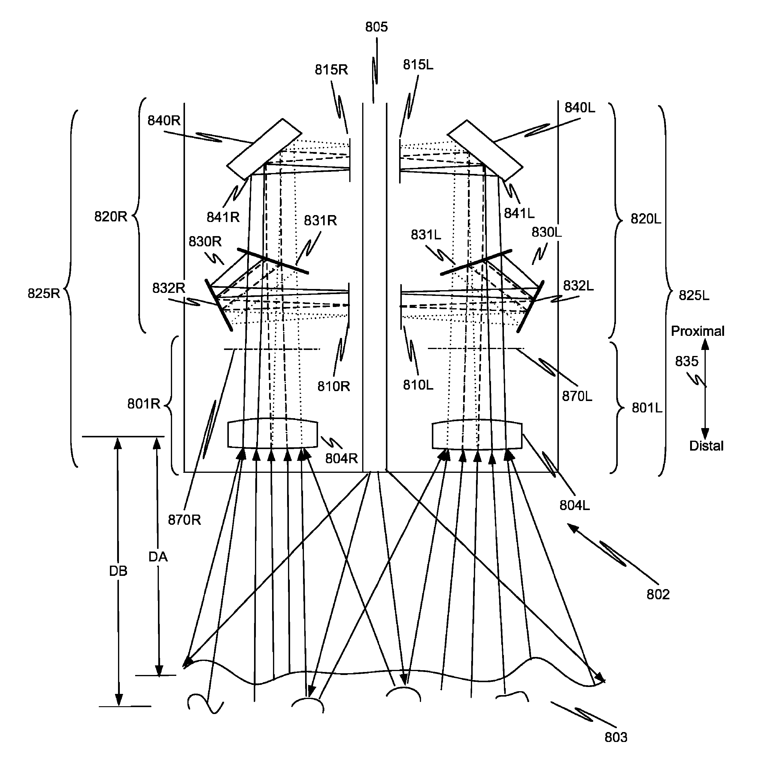
[0063]As used herein, electronic stereoscopic imaging includes the use of two imaging channels (i.e., one channel for left side images and another channel for right side images).

[0064]As used herein, a stereoscopic optical path includes two channels (e.g., channels for left and right images) for transporting light from an object such as tissue to be imaged. The light transported in each channel represents a different view (stereoscopic left or right) of a scene in the surgical field. Each one of the stereoscopic channels may include one, two, or more optical paths, and so light transported along a single stereoscopic channel can form one or more images. For example, for the left stereoscopic channel, one left side image may be captured from light traveling along a first optical path, and a second left side image may be captured from light traveling along a second optical path. Without loss of generality or applicability, the aspects described more completely below also could be used...


PUM


Abstract

In a minimally invasive surgical system, an image capture unit includes a prism assembly and sensor assembly. The prism assembly includes a beam splitter, while the sensor assembly includes coplanar image capture sensors. Each of the coplanar image capture sensors has a common front end optical structure, e.g., the optical structure distal to the image capture unit is the same for each of the sensors. A controller enhances images acquired by the coplanar image capture sensors. The enhanced images may include (a) visible images with enhanced feature definition, in which a particular feature in the scene is emphasized to the operator of minimally invasive surgical system; (b) images having increased image apparent resolution; (c) images having increased dynamic range; (d) images displayed in a way based on a pixel color component vector having three or more color components; and (e) images having extended depth of field.

Description

BACKGROUND[0001]1. Field of Invention[0002]Aspects of this invention are related generally to endoscopic imaging and are more particularly related to capturing light from a common front end optical structure in a plurality of coplanar image capture sensors.[0003]2. Related Art[0004]The da Vinci® Surgical Systems, commercialized by Intuitive Surgical, Inc., Sunnyvale, Calif., are minimally invasive teleoperated surgical systems that offer patients many benefits, such as reduced trauma to the body, faster recovery and shorter hospital stay. One key component of a da Vinci® Surgical System (e.g., the model IS3000, da Vinci® Si HD) is a capability to provide two-channel (i.e., left and right) video capture and display of visible images to provide stereoscopic viewing for the surgeon. Such electronic stereoscopic imaging systems may output high definition video images to the surgeon, and may allow features such as zoom to provide a “magnified” view that allows the surgeon to identify spe...

Claims


Application Information

Patent Timeline
Patent Type & Authority Patents(United States)
IPC IPC(8): A61B1/06A61B1/00A61B1/04H04N13/239
CPCA61B1/00193A61B1/045A61B1/051A61B1/00096A61B1/00009A61B1/055H04N13/239H04N13/254A61B1/000094A61B1/000095G02B23/04G02B23/2484
Inventor MCDOWALL, IAN
Owner INTUITIVE SURGICAL OPERATIONS INC
Why Eureka
Try Eureka