Delay circuit having reduced duty cycle distortion

a delay circuit and duty cycle technology, applied in the field of delay circuitry, can solve problems such as duty cycle distortion in variable delay lines, and achieve the effect of reducing duty cycle distortion, without significantly affecting performance and/or area

Inactive Publication Date: 2014-03-25
AVAGO TECH INT SALES PTE LTD
View PDF8 Cites 3 Cited by
  • Summary
  • Abstract
  • Description
  • Claims
  • Application Information

AI Technical Summary

Benefits of technology

[0006]Illustrative embodiments of the present invention meet the above-noted need by providing techniques for beneficially reducing duty cycle distortion in a delay circuit without significantly impacting performance and / or area. To accomplish this, embodiments of the invention eliminate multiplexers and associated multiplexer decoding circuitry often used to select a desired delay signal path in a delay circuit. Instead, each of the delay signal paths in the delay circuit are configured to be substantially identical to one another by advantageously utilizing tri-statable switching elements for selecting a desired delay signal path in the delay circuit.

Problems solved by technology

Duty cycle distortion due to different propagation delay times for rising and falling edges can introduce duty cycle distortion in variable delay lines.

Method used


Image

  • Delay circuit having reduced duty cycle distortion
  • Delay circuit having reduced duty cycle distortion
  • Delay circuit having reduced duty cycle distortion

Examples


Embodiment Construction

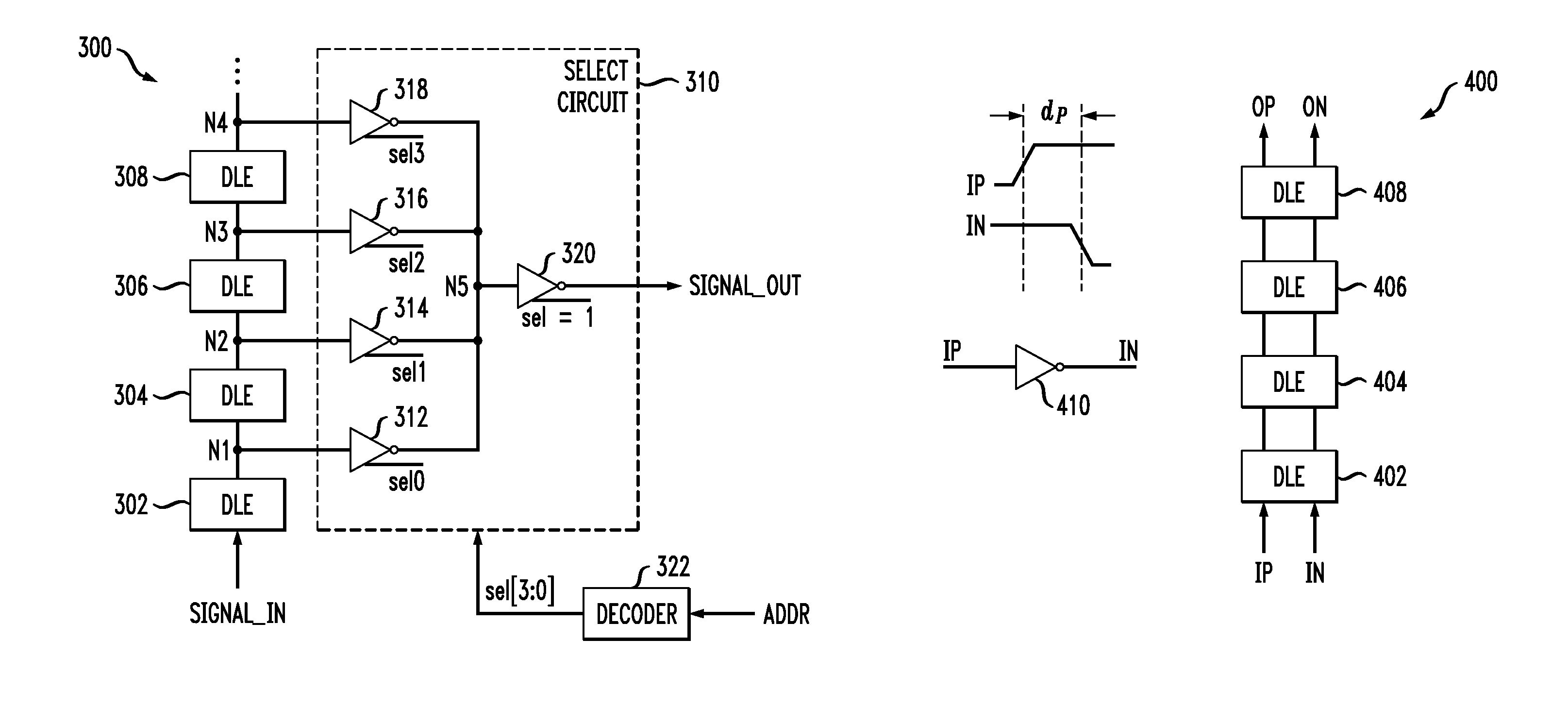
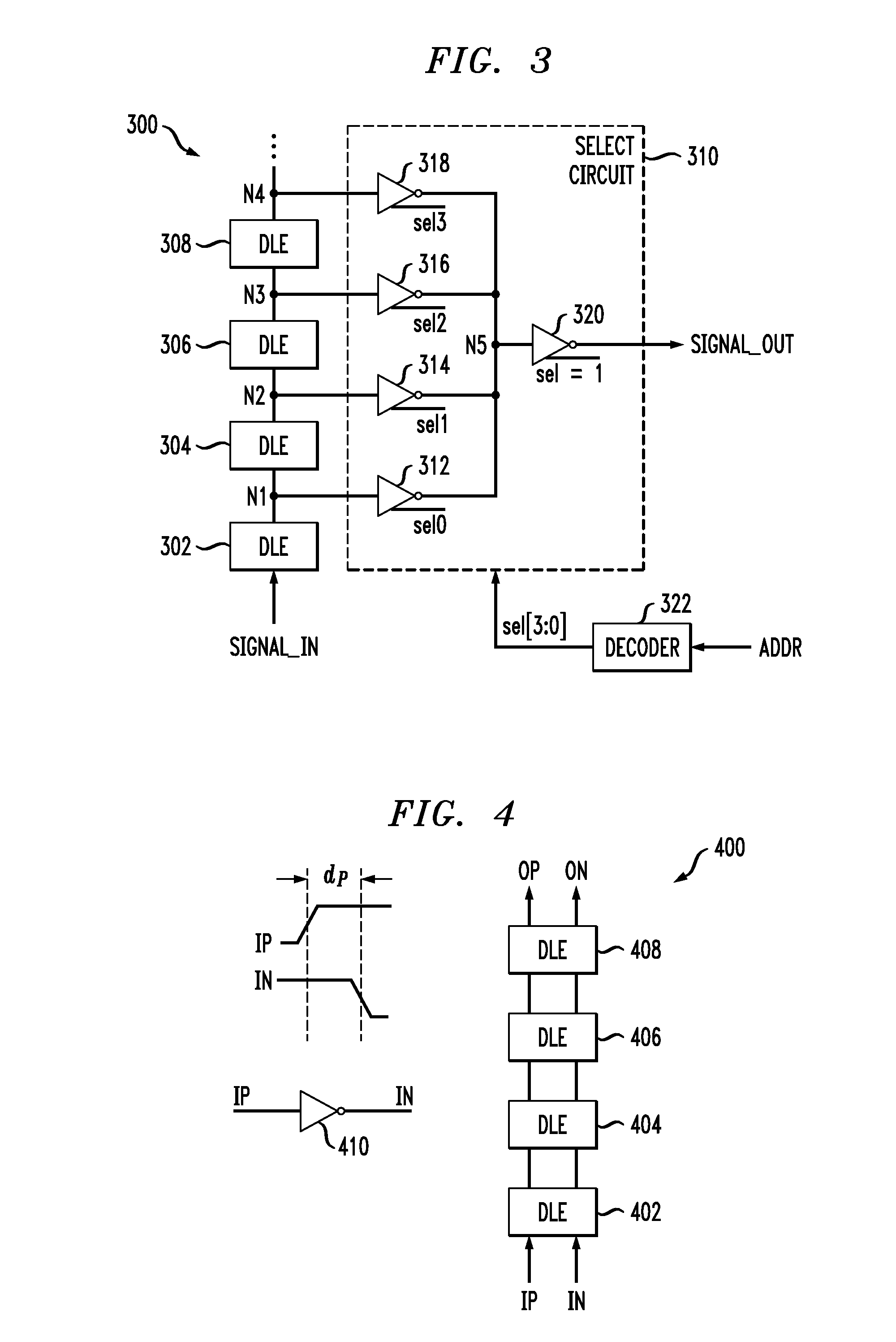
[0014]The present invention will be described herein in the context of exemplary delay line circuits. It is to be understood, however, that the techniques of the present invention are not limited to the circuits shown and described herein. Rather, embodiments of the invention are directed to techniques for reducing duty cycle distortion in a delay line, without significantly impacting performance and / or area of the circuit. Although preferred embodiments of the invention may be fabricated in a silicon wafer, embodiments of the invention can alternatively be fabricated in wafers comprising other materials, including but not limited to Gallium Arsenide (GaAs), Indium Phosphide (InP), etc.

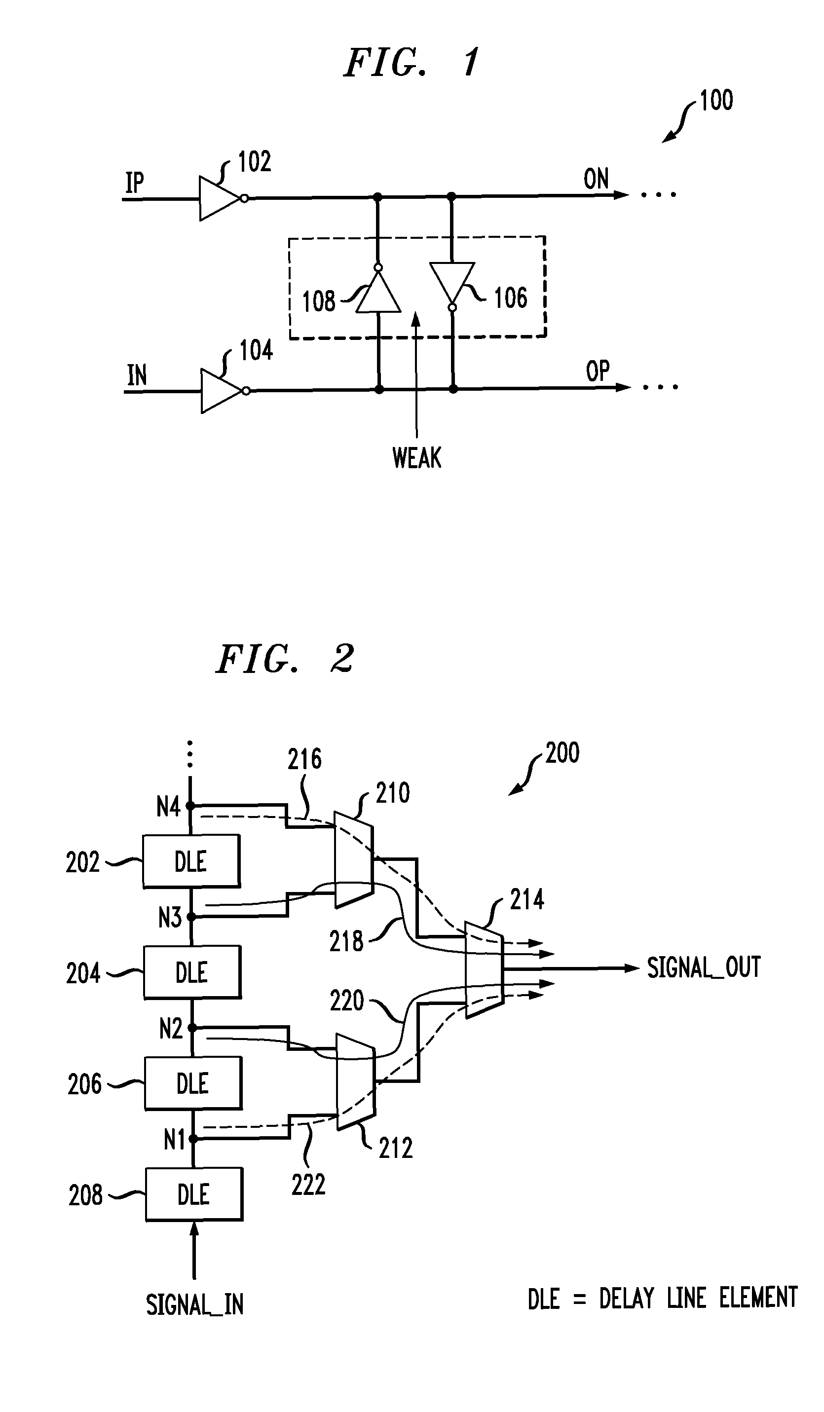
[0015]As previously stated, the illustrative differential delay element 100 shown in FIG. 1, which may be referred to herein as a delay line element (DLE), represents one approach to forming a delay line having reduced signal skew. Unfortunately, one disadvantage with this DLE is that, due to its diff...


PUM


Abstract

A delay circuit having reduced duty cycle distortion is provided. The delay circuit includes a plurality of delay elements connected together in a series configuration. Each of the delay elements has a prescribed delay associated therewith. The delay circuit further includes a controller connected to respective outputs of the delay elements. The controller is configured such that signal paths between the respective outputs of the delay elements and an output of the controller have delays that are substantially the same relative to one another. Each of the signal paths has a tri-statable switching element associated therewith.

Description

CROSS-REFERENCE TO RELATED APPLICATION(S)[0001]This application claims the benefit of U.S. Provisional Application Ser. No. 60 / 984,170, filed on Oct. 31, 2007, the disclosure of which is incorporated by reference herein.FIELD OF THE INVENTION[0002]The present invention relates generally to the electrical and electronic arts, and more particularly relates to delay circuitry.BACKGROUND OF THE INVENTION[0003]The use of programmable delay lines in integrated circuits for signal de-skewing is well-known. For example, FIG. 1 illustrates a conventional approach to reducing signal skew by forming a differential delay line which incorporates a differential delay element 100 having reduced duty cycle distortion. As apparent from the figure, this approach employs two inverter chains, a first inverter chain including a first inverter 102, and a second inverter chain including a second inverter 104. An input signal, IP, to the first inverter 102 may be a complementary clock signal while a second...

Claims


Application Information

Patent Timeline
Patent Type & Authority Patents(United States)
IPC IPC(8): H03H11/26
CPCH03K2005/00234H03K5/132H03K2005/00136H03K5/133
Inventor CHLIPALA, JAMES D.SEGAN, SCOTT A.
Owner AVAGO TECH INT SALES PTE LTD
Why Eureka
Try Eureka