Delay Circuit Having Reduced Duty Cycle Distortion
- Summary
- Abstract
- Description
- Claims
- Application Information
AI Technical Summary
Benefits of technology
Problems solved by technology
Method used
Image
Examples
Embodiment Construction
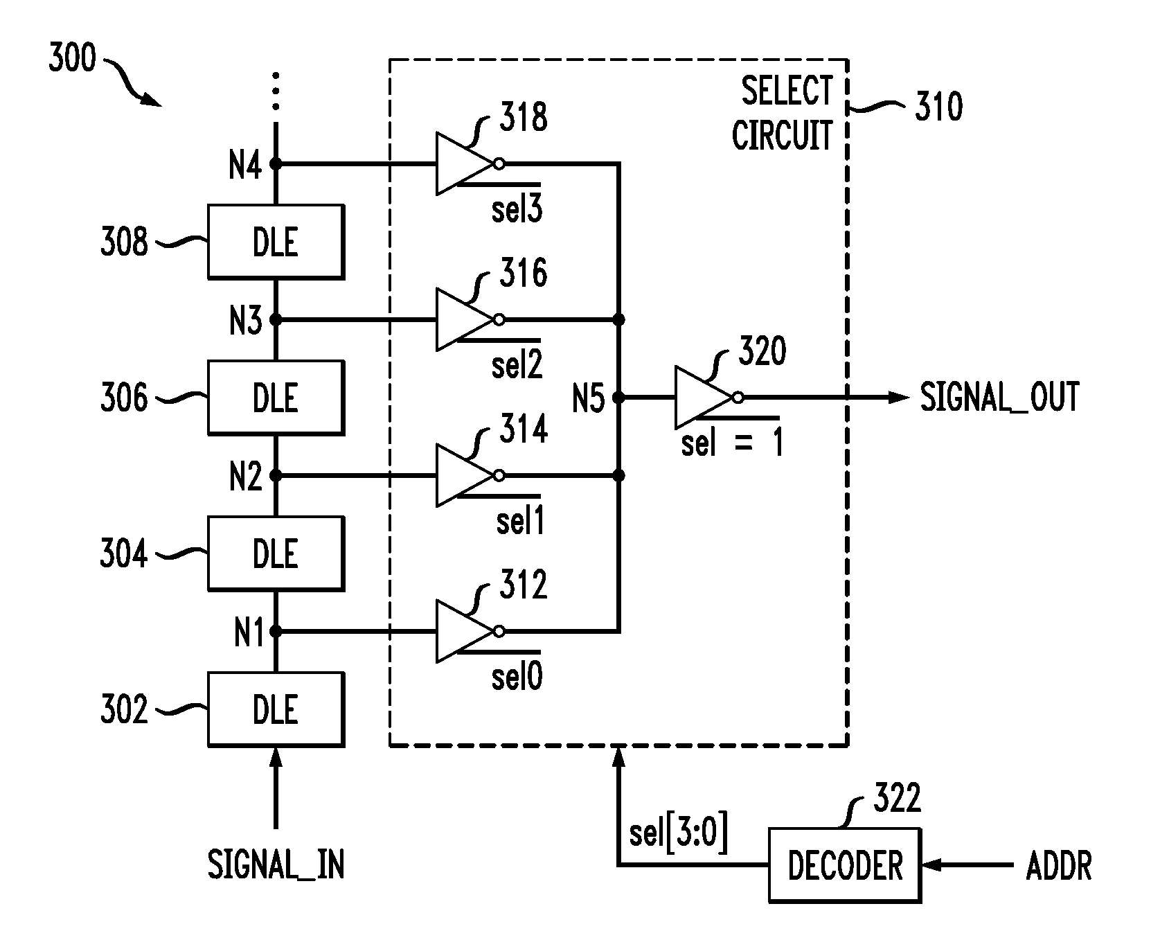
[0014]The present invention will be described herein in the context of exemplary delay line circuits. It is to be understood, however, that the techniques of the present invention are not limited to the circuits shown and described herein. Rather, embodiments of the invention are directed to techniques for reducing duty cycle distortion in a delay line, without significantly impacting performance and / or area of the circuit. Although preferred embodiments of the invention may be fabricated in a silicon wafer, embodiments of the invention can alternatively be fabricated in wafers comprising other materials, including but not limited to Gallium Arsenide (GaAs), Indium Phosphide (InP), etc.
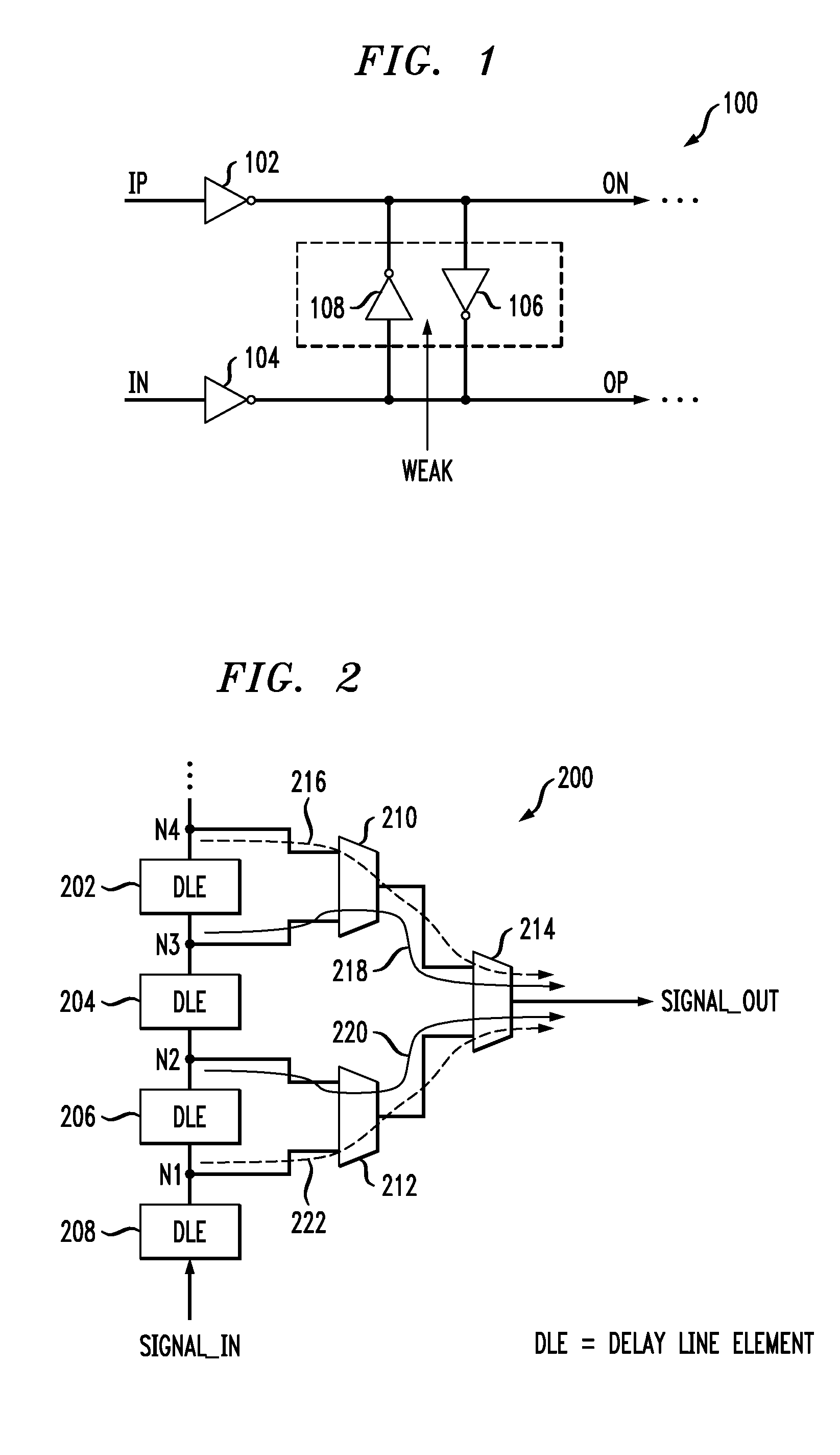
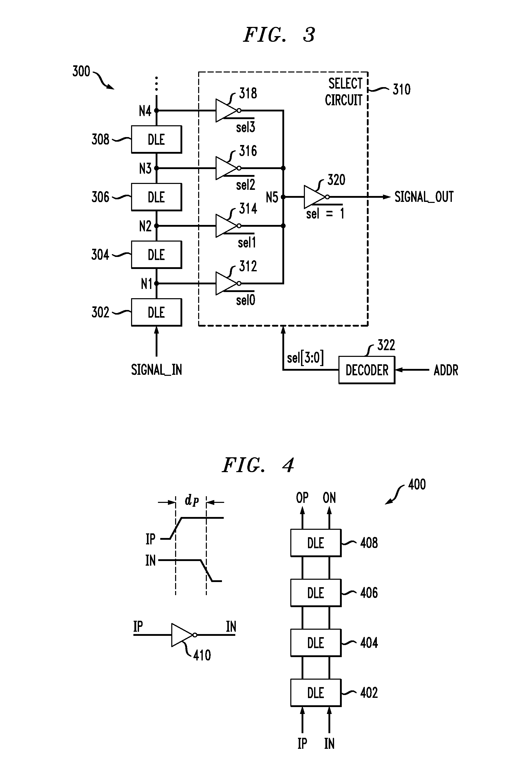
[0015]As previously stated, the illustrative differential delay element 100 shown in FIG. 1, which may be referred to herein as a delay line element (DLE), represents one approach to forming a delay line having reduced signal skew. Unfortunately, one disadvantage with this DLE is that, due to its diff...
PUM
 Abstract
Description
Claims
Application Information
 - R&D
- Intellectual Property
- Life Sciences
- Materials
- Tech Scout
- Unparalleled Data Quality
- Higher Quality Content
- 60% Fewer Hallucinations
Browse by: Latest US Patents, China's latest patents, Technical Efficacy Thesaurus, Application Domain, Technology Topic, Popular Technical Reports.
© 2025 PatSnap. All rights reserved.Legal|Privacy policy|Modern Slavery Act Transparency Statement|Sitemap|About US| Contact US: help@patsnap.com


