
Circuits for and methods of reducing duty-cycle distortion in an integrated circuit implementing dual-edge clocking

a dual-edge clocking and integrated circuit technology, applied in the direction of pulse manipulation, pulse technique, generating/distributing signals, etc., can solve the problems of significant power consumption of routing clock signals in an integrated circuit, duty-cycle distortion (dcd) associated with rising and falling edges of clock signals, and the duty cycle of clock signals is created. to achieve the effect of reducing duty-cycle distortion

Active Publication Date: 2017-02-21
XILINX INC
View PDF3 Cites 7 Cited by
  • Summary
  • Abstract
  • Description
  • Claims
  • Application Information

AI Technical Summary

Benefits of technology

The patent describes a circuit that minimizes distortion in an integrated circuit that uses dual-edge clocking. It includes elements that route data, register circuits that store data, and a clock circuit that sends a signal to the register circuits. The circuit also includes a pulsed-controlled register circuit that stores data at a different time than the clock signal. The technical effects of this circuit include reducing duty-cycle distortion and improving data transmission accuracy.

Problems solved by technology

Significant power is consumed by routing clock signals in an integrated circuit.
For example, duty-cycle distortion (DCD) associated with rising and falling edges of a clock signal occurs due to the difference in rising and falling edge signal propagation in the clock network.
The difference between rising and falling edge propagation will accumulate at each stage, creating distortion in the duty cycle of the clock signal.
When using both rising and falling edges to register data using a clock signal for example, there is a time penalty (either positive or negative) between consecutive rising and falling edges as a result of duty-cycle distortion.
But with dual-edge clocking, duty-cycle distortion will add time to odd edge clock skew and subtract time from even edge clock skew, or vice versa, depending on rising / falling delay propagation ratio.
As a result, duty-cycle distortion reduces the operating speed of the integrated circuit.

Method used


Image

  • Circuits for and methods of reducing duty-cycle distortion in an integrated circuit implementing dual-edge clocking
  • Circuits for and methods of reducing duty-cycle distortion in an integrated circuit implementing dual-edge clocking
  • Circuits for and methods of reducing duty-cycle distortion in an integrated circuit implementing dual-edge clocking

Examples


Embodiment Construction

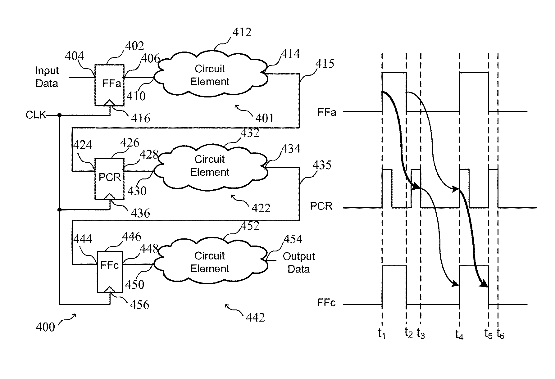
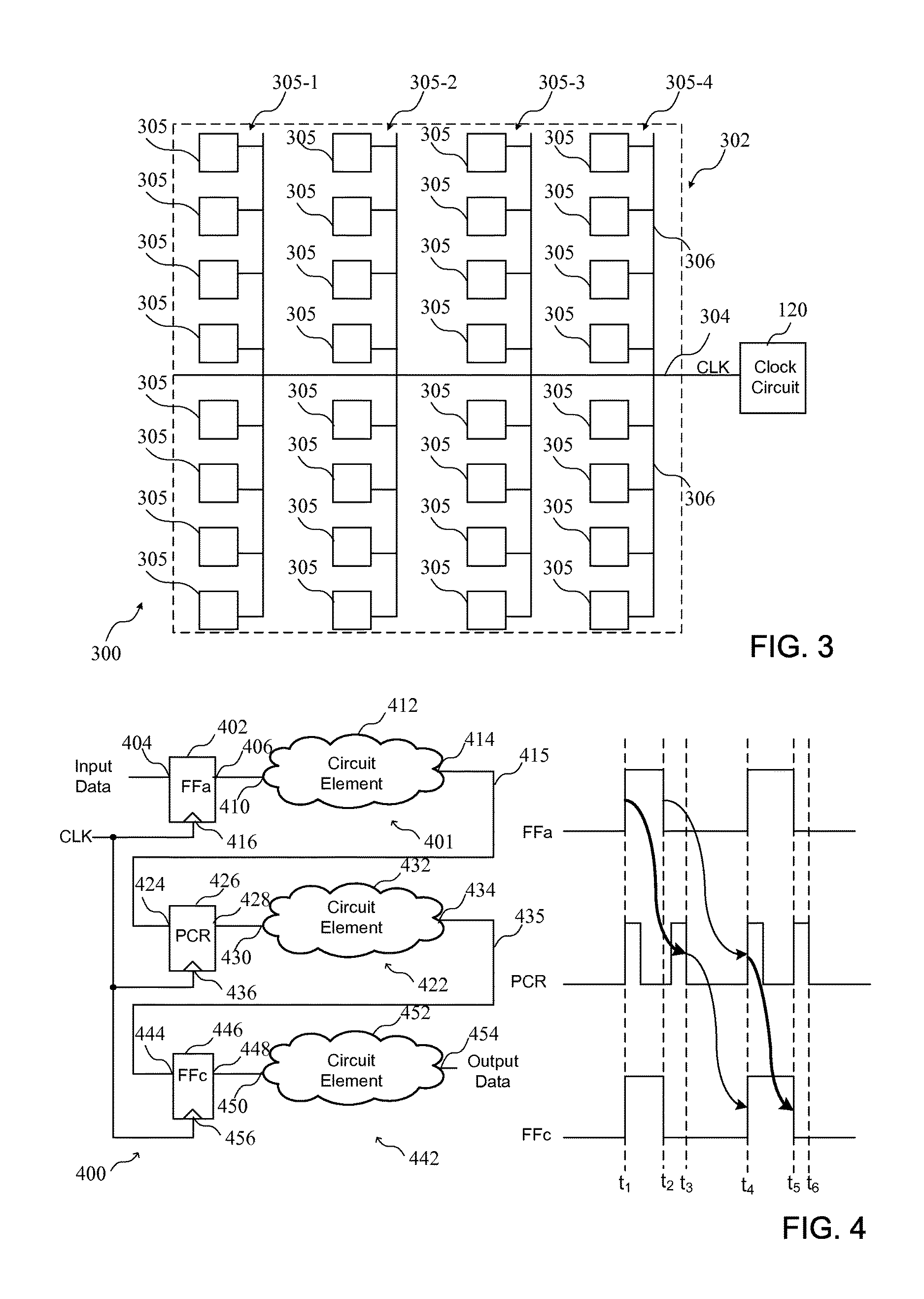
[0027]The circuits and methods set forth below reduce power consumed by routing clock signals in an integrated circuit, and mitigate the penalty due to duty-cycle distortion when using dual-edge clocking. Dual-edge clocking is used to reduce dynamic power consumed in distributing a clock signal in an integrated circuit by distributing the clock signal at half speed. Pulse-controlled registers that trigger on both rising and falling edges can be selectively implemented to reduce the impact of duty-cycle distortion. That is, a time penalty as a result of duty-cycle distortion can be reduced by ensuring that a pulse generated by a pulse-controlled register is sufficient to provide an offset for the duty-cycle distortion. By way of example, a method of mitigating the penalty due to duty-cycle distortion can include identifying duty-cycle distortion in the clock signal at a clock input of a register, and coupling a pulsed output of a pulse generator, rather than the clock signal exhibiti...


PUM


Abstract

A circuit for reducing duty-cycle distortion in an integrated circuit implementing dual-edge clocking is described. The circuit also comprises a plurality of circuit elements that enable the routing of data generated at outputs of the circuit elements; a plurality of register circuits that store data at outputs of the plurality of circuit elements; a clock circuit routing a clock signal to clock inputs of the plurality of register circuits; and a pulsed-controlled register circuit coupled to an output of a circuit element and generating a pulsed output coupled to a clock input of a register of the pulse-controlled register circuit; wherein the pulsed output is coupled to the clock input of the register to enable the pulse-controlled register circuit to store data at a time that is different than an edge of the clock signal. A method of reducing duty-cycle distortion in an integrated circuit implementing dual-edge clocking is also described.

Description

FIELD OF THE INVENTION[0001]The present invention relates generally to integrated circuit devices, and in particular, to circuits for and methods of reducing duty-cycle distortion in an integrated circuit implementing dual-edge clocking.BACKGROUND OF THE INVENTION[0002]Clock networks are an important part of implementing circuits in integrated circuit devices. Significant power is consumed by routing clock signals in an integrated circuit. Further, a clock signal can be altered as it is routed in a clock network of the integrated circuit. For example, duty-cycle distortion (DCD) associated with rising and falling edges of a clock signal occurs due to the difference in rising and falling edge signal propagation in the clock network. There is generally a difference between the strength of a PMOS transistor (used for a 0 to 1 transition) and strength of an NMOS transistor (used for a 1 to 0 transition). This variation is largely due to materials used in the device and physical layout v...

Claims


Application Information

Patent Timeline
Patent Type & Authority Patents(United States)
IPC IPC(8): H03K3/017H03K3/356
CPCH03K3/017H03K3/356G06F1/10H03K3/356156H03K5/1565
Inventor GANUSOV, ILYA K.DEVLIN, BENJAMIN S.
Owner XILINX INC
Learn More