Delay line with delay cells having improved gain and in built duty cycle control and method thereof

Inactive Publication Date: 2007-12-13
COSMIC CIRCUITS PRIVATE LIMITED
View PDF19 Cites 6 Cited by
  • Summary
  • Abstract
  • Description
  • Claims
  • Application Information

AI Technical Summary

Benefits of technology

[0010]Embodiments of the invention described herein provide a delay line with identical dela

Problems solved by technology

However, operating the delay line at high frequencies usually results in a loss of ‘gain’ and ‘duty cycle distortion’ in an output of a current or voltage controlled delay cell.
Duty cycle distortion may occur because of mismatch between rising and falling edge delays of the delay cell.
In the application of this delay line in a DLL, the frequency range of operation of the DLL gets limited.
Further, delay lines with large number of delay cells have considerable duty cycle distortion, thereby limiting the

Method used


Image

  • Delay line with delay cells having improved gain and in built duty cycle control and method thereof
  • Delay line with delay cells having improved gain and in built duty cycle control and method thereof
  • Delay line with delay cells having improved gain and in built duty cycle control and method thereof

Examples


Embodiment Construction

[0020]Embodiments of the invention provide a delay line with increased gain controllability, and reduced duty cycle distortion.

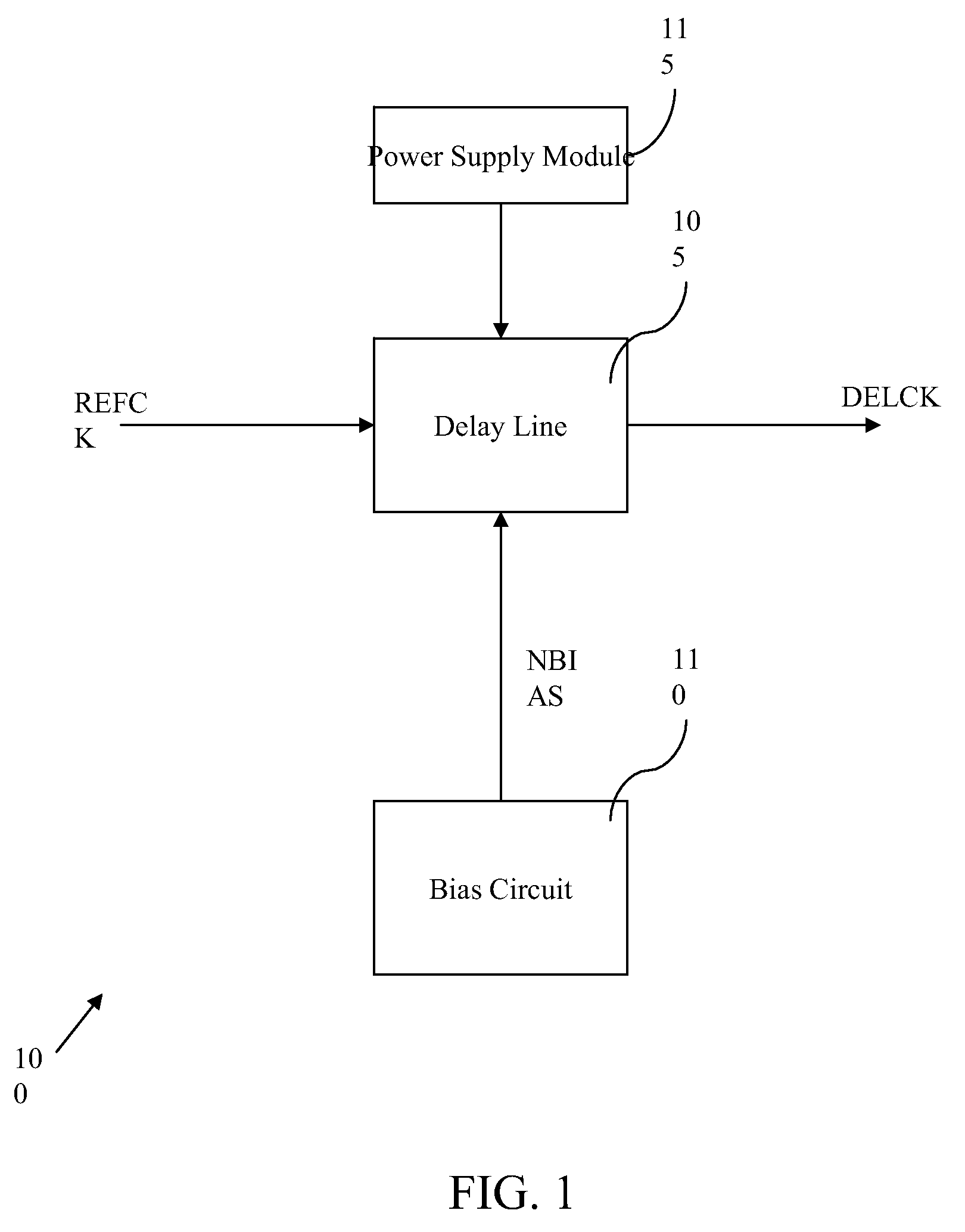
[0021]FIG. 1 is a block diagram illustrating an example environment 100, in which embodiments of the invention may be practiced. The environment 100 includes a delay line 105, a bias circuit 110, and a power supply module 115. The delay line 105 receives a reference clock signal ‘REFCK’ at its input. The bias circuit 110 is coupled to the delay line 105 and provides a voltage bias signal ‘NBIAS’ to the delay line 105. The NBIAS controls a delay of the delay line 105. The power supply module 115, for example, a Low Drop Out (LDO) regulator provides a supply voltage to the delay line 105.

[0022]The delay line 105 includes a sequence of identical delay cells that generate the delay. A delay cell has been explained in details in conjunction with FIG. 2.

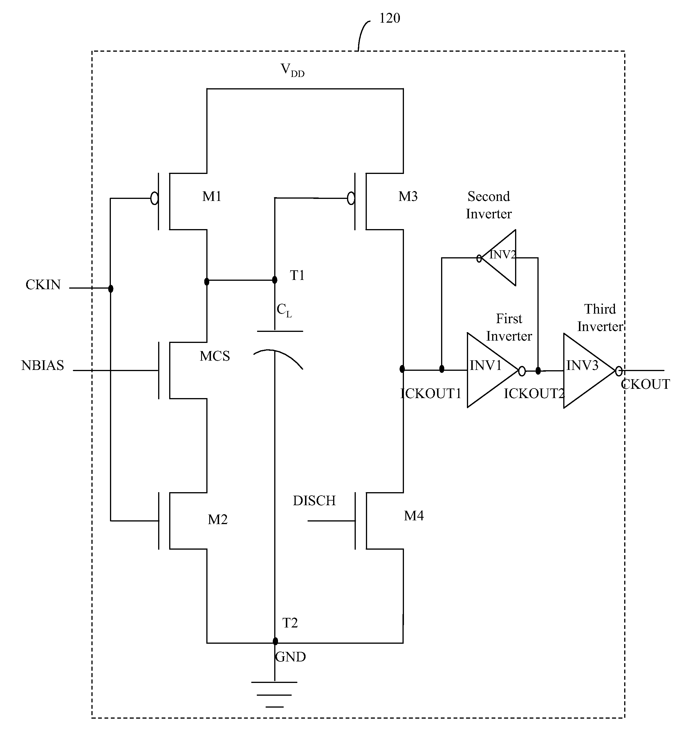
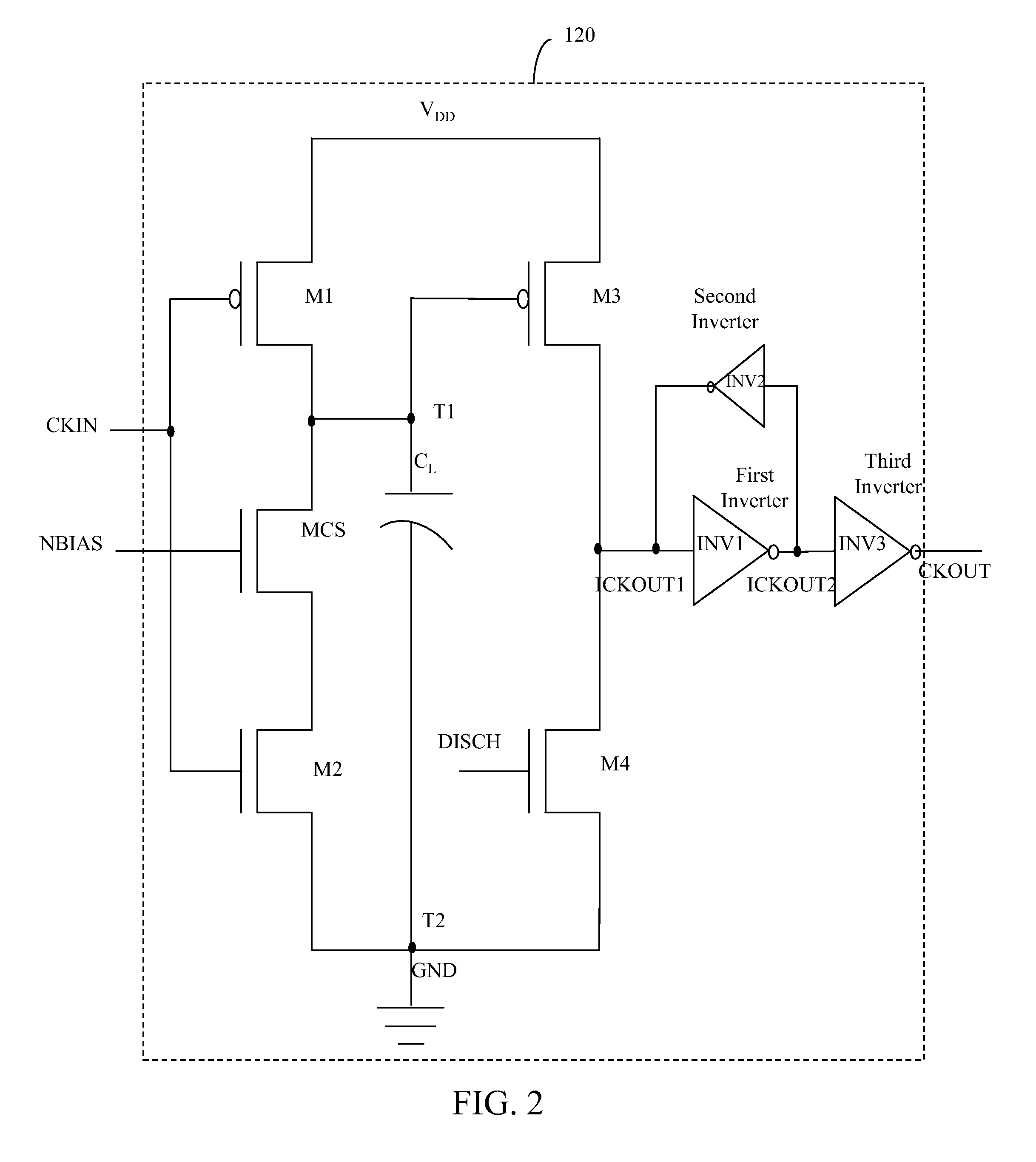
[0023]FIG. 2 is a schematic circuit diagram of a delay cell 120 of the delay line 105 in accordance with an embo...


PUM


Abstract

A delay line including a sequence of identical delay cells with improved gain and in built duty cycle distortion control and a method thereof is disclosed. Each delay cell of the sequence includes a current source, four transistors, and a load capacitor. A gate of the current source receives a voltage bias that controls a delay of the delay cell. A drain of the first transistor is connected to the drain of the current source. The first and second transistor gates receive an input clock signal. The second transistor drain is connected to the source of the current source. The third transistor gate and the load capacitor are also connected to the drain of the current source. The fourth transistor drain is connected to the third transistor drain. The fourth transistor gate is coupled to an output of a second consecutive delay cell for duty cycle distortion control.

Description

CROSS-REFERENCE TO RELATED APPLICATIONS[0001]This application claims priority to Indian Provisional Patent Application No. 1007 / CHE / 2006, filed Jun. 9, 2006, and Indian Non-Provisional Patent Application No. 1181 / CHE / 2007, filed Jun. 8, 2007, which are incorporated herein by reference.BACKGROUND[0002]1. Technical Field[0003]Embodiments of the invention relate generally to delay lines and more particularly to delay cells with improved gain and reduced duty cycle distortion for a wide range of delays.[0004]2. Prior Art[0005]A delay line includes several delay cells connected in series that generate a required delay. Delay lines constitute several electronic devices, for example Delay Locked Loops (DLLs), which have a wide variety of electronic applications such as clock and data recovery, frequency synthesis, and generation of clock pulses for sampling in high speed Analog-to-Digital Converters (ADCs). A delay cell constitutes a building block of the delay line. The number of delay ce...

Claims


Application Information

Patent Timeline
IPC IPC(8): H03H11/26
CPCH03H11/265H03K2005/00045H03K5/1565H03K5/133
Inventor BHOWMIK, PRASENJITKRISHNAN, SUNDARARAJANSRIRAM, G.
Owner COSMIC CIRCUITS PRIVATE LIMITED
Why Eureka
Try Eureka