Differential ring oscillator-type voltage control oscillator

Inactive Publication Date: 2013-01-17
KOUYAMA KUNIHIKO
View PDF3 Cites 6 Cited by
  • Summary
  • Abstract
  • Description
  • Claims
  • Application Information

AI Technical Summary

Benefits of technology

[0011]According to the present invention, an amplitude is limited by the voltage applied from the inverting amplifier. The amplitude limiting shortens the rise time and fall time of an oscillation signal, thereby reducing the jitter of the voltage control oscillator. The amplitude limiting also eliminates fluctuations in the power supply voltage of the ring oscillator at a high level of the oscillation signal, so that a PSRR (Power Supply Rejection Ratio) decreases. Furthermore, the current is stabilized by the current driving the ring oscillator by means of the differential inverters, so that fluctuations in oscillatory frequency are reduced and lower jitter is obtained. However, the amplitude limiting alone cannot increase the gain of the voltage control oscillator or extend the variable range of oscillatory frequencies. Hence, in the present invention, an amplitude from each of the differential inverters is controlled by a voltage from the inverting amplifier, thereby increasing the gain of the voltage control oscillator and

Problems solved by technology

However, the amplitude limiting alone cannot increase the gain of the voltag

Method used


Image

  • Differential ring oscillator-type voltage control oscillator
  • Differential ring oscillator-type voltage control oscillator
  • Differential ring oscillator-type voltage control oscillator

Examples


Embodiment Construction

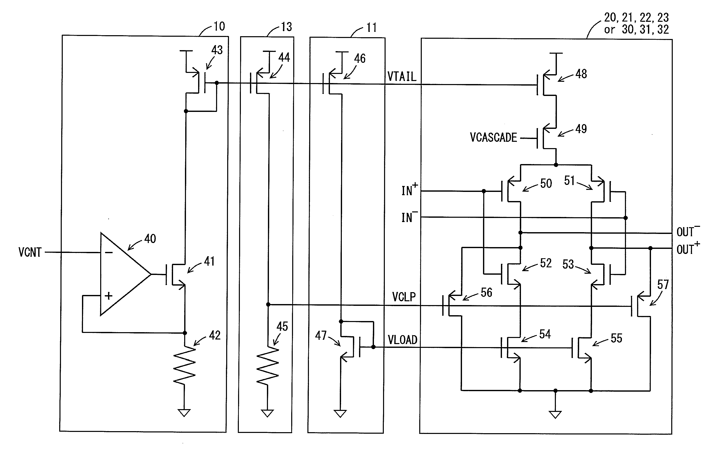
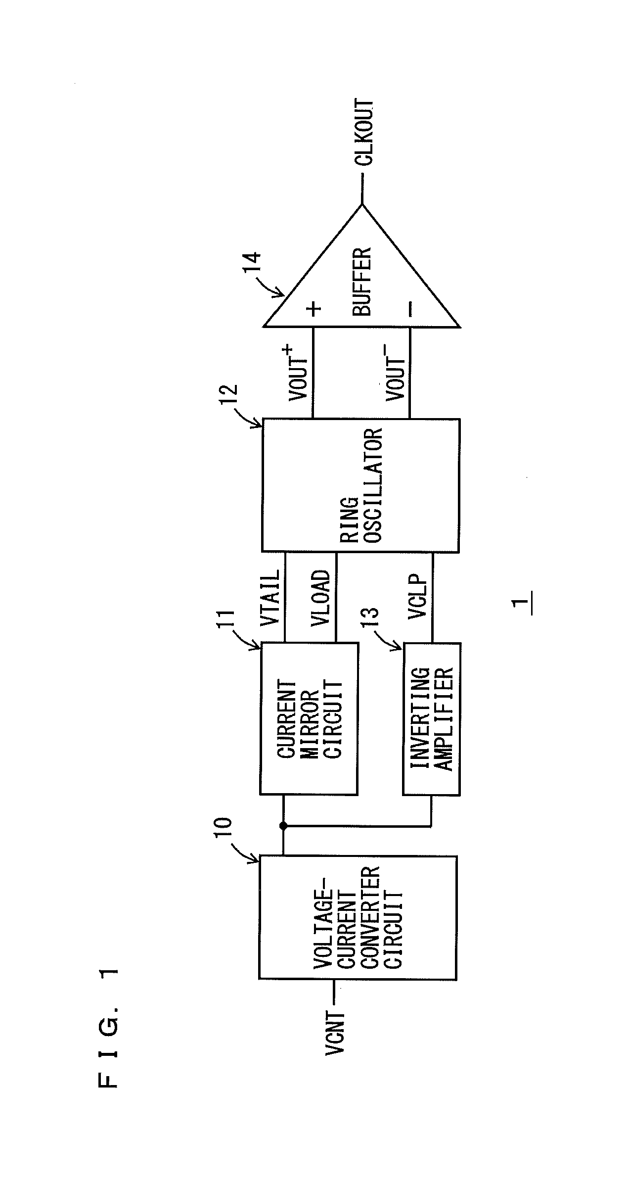
[0020]FIG. 1 is a block diagram showing the functional configuration of a voltage control oscillator 1 according to an embodiment of the present invention. The voltage control oscillator 1 includes a voltage-current converter circuit 10, a current mirror circuit 11, a ring oscillator 12, an inverting amplifier 13, and a buffer 14. For example, the voltage control oscillator 1 may be used in a PLL circuit provided with a phase detector, a charge pump, and a feedback divider. The phase detector detects, for example, a phase difference between a reference oscillation signal and a feedback signal from the feedback divider. The charge pump inputs a control voltage VCNT to the voltage control oscillator 1 according to the detected phase difference. The voltage control oscillator 1 controls an oscillatory frequency according to the control voltage VCNT. In the present invention, the application of the voltage control oscillator 1 is not limited to the PLL.

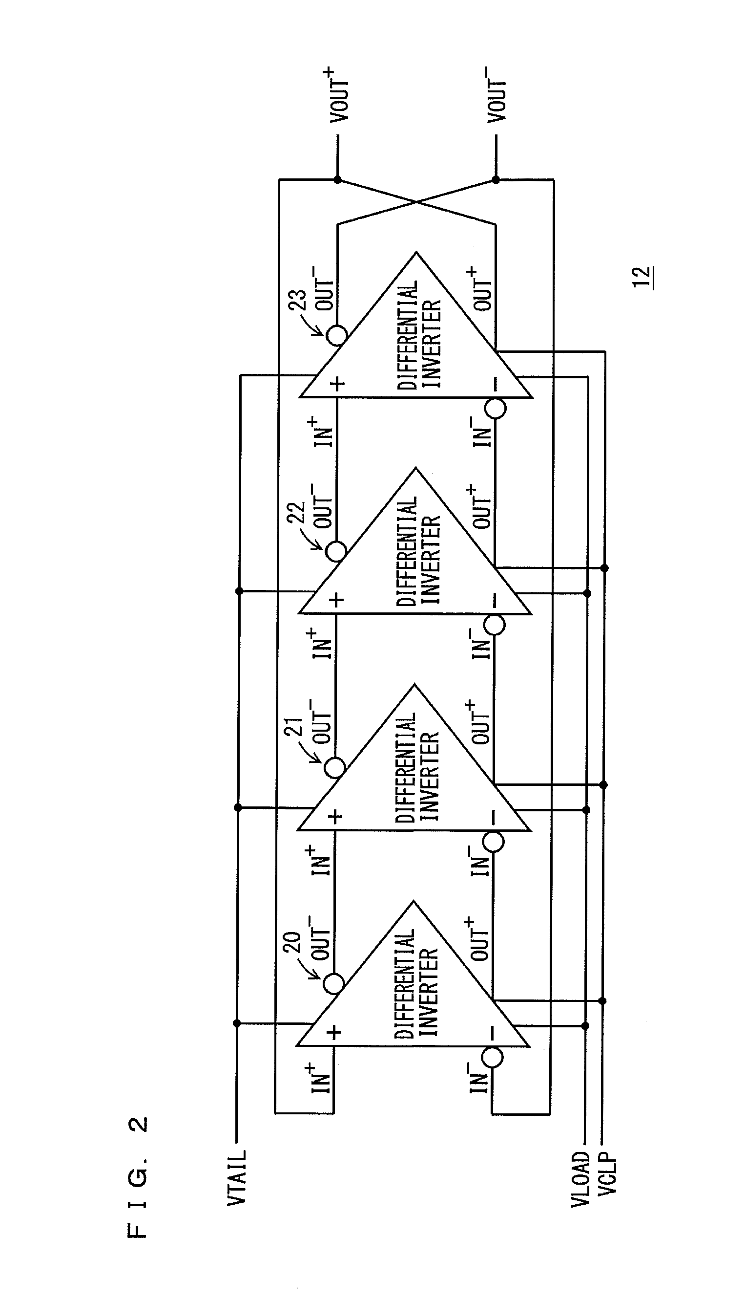
[0021]FIG. 2 is a block diagram sh...


PUM


Abstract

A voltage control oscillator according to the present invention includes: a voltage-current converter circuit that converts an inputted voltage to a current according to the value of the voltage; a current mirror circuit; a ring oscillator including differential inverters connected in multiple stages; an inverting amplifier; and a buffer. The ring oscillator outputs, from each of the differential inverters, a signal amplitude-limited by a “current converted by the voltage-current converter circuit and the current mirror circuit” and a “voltage applied from the inverting amplifier” and the ring oscillator outputs an oscillatory frequency in response to the output signal.

Description

BACKGROUND OF THE INVENTION[0001]1. Technical Field[0002]The present invention relates to a voltage control oscillator (VCO) in a phase-locked loop (PLL) circuit.[0003]2. Background Art[0004]In interface receiver circuits of HDMI and S / PDIF, transfer clock frequency ranges tend to increase. A PLL is used to recover a clock from a received signal. In use of a PLL, a voltage control oscillator (VCO) with a wide frequency variable range and low jitter is necessary.[0005]In Patent Literature 6 and Patent Literature 7, a ring oscillator including a single-ended inverter has odd-numbered stages. In Patent Literature 1, the amplitude of a differential output (62) is fixed by clamping transistors (104, 106) in an inverter (48). In Patent Literature 5, a high level of an inverter is set to a reference potential to limit amplitude. The load of a differential inverter in a ring oscillator according to the related art uses a resistance or an on-resistance of a transistor in a non-saturated regi...

Claims


Application Information

Patent Timeline
IPC IPC(8): H03L7/08H03K3/03
CPCH03L7/0995H03K3/0322
Inventor KOUYAMA, KUNIHIKO
Owner KOUYAMA KUNIHIKO
Why Eureka
Try Eureka