Log-periodic antenna

a technology of logperiod antennas and antennas, which is applied in the direction of antennas, non-resonant long antennas, and electric long antennas. it can solve the problems of inconvenient pattern receiving directional signals, inefficient illumination of reflector surfaces, and serious transmission losses between antennas and remote electronics. it achieves the effect of reducing cross-polarization coupling

Inactive Publication Date: 2005-10-04
RGT UNIV OF CALIFORNIA
View PDF41 Cites 7 Cited by
  • Summary
  • Abstract
  • Description
  • Claims
  • Application Information

AI Technical Summary

Benefits of technology

[0028]In addition to embodiments including an interior conductive shield, further embodiments of the present invention present improved designs for the individual arms of the log-periodic antenna, including in some embodiments a finline attachment that results, for example, in decreased cross-polarization coupling between the arms of the antenna.

Problems solved by technology

In such cases, transmission losses occurring between the antenna and remote electronics can be a serious concern.
While a nearly unipolar far-field pattern with high gain and linear polarization can be achieved with a planar dipole array, the 3 dB contour of the main lobe is elliptical, making it inefficient for illuminating (or collecting energy from) reflectors which are typically surfaces of rotation.
This pattern is inconvenient for receiving directional signals.
Since transmission lines are conductors, they can disrupt the radiation and transmission modes of the antenna.
There are distinct disadvantages to the current transmission line attachments to non-planar log-periodic antennas, among which are the following:a) Transmission lines attached to the log-periodic antenna terminals typically are routed along the mid-line of one of the antenna arms and out the back (wide end) of the antenna where the lines are attached to an amplifier receiver or transmitter.
However, any electronic module placed between the antenna arms (inside the wedge geometry) close to the antenna terminals will disrupt the transmission mode feeding the active region of the antenna structure.

Method used


Image

  • Log-periodic antenna
  • Log-periodic antenna
  • Log-periodic antenna

Examples


examples

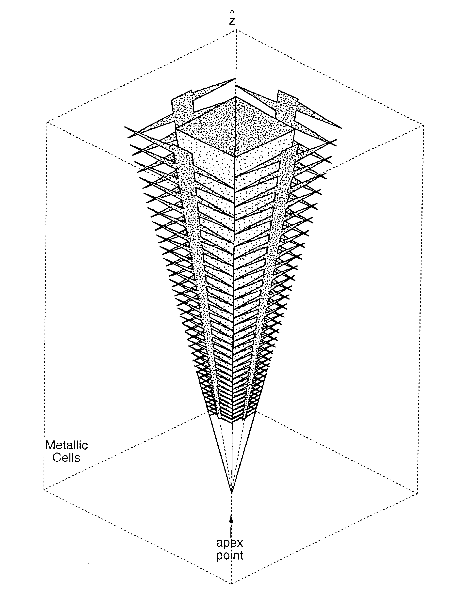
[0077]Tests and computer simulations of dual feed, linearly polarized log-periodic antennas as described herein have been carried out for numerical parameters and structures as given above. That is, antennas were studied with antenna arms as defined by FIG. 5 with a log-periodic scale factor of 0.975 and a boom opening angle of 3.6 degrees (FIG. 12(A)). No finline attachment was employed. The antenna has a pyramidal configuration as depicted in FIG. 8 with an apex angle of approximately 20 degrees. A square, pyramidal conducting shield is also included with an apex angle of approximately 10 degrees. FIG. 13 demonstrates that this antenna configuration (with no finline attachment, LP1) radiates approximately 80% of its power within the 13 dB intensity contour of the main beam. Effectively, this is the fraction of power that can be efficiently coupled from a parabolic reflector dish to the feed. As shown in FIG. 13, the remaining 20% of the power is radiated in distinct sidelobes grea...


PUM


Abstract

A self-similar log-periodic antenna is described comprising a plurality of substantially triangular conductive elements, 4, symmetrically disposed in either planar or curved configurations about a central conductive boom to form an antenna arm. Two or more antenna arms are assembled into an antenna by symmetrically locating such antenna arms substantially in the shape of a pyramid (for planar arms) or in a conical shape (for curved arms). Some embodiments include a conductive fin, 5, to reduce cross-polarization coupling between antenna arms. Some embodiments include a grounded conductive shield on the interior of the antenna providing electromagnetic shielding for the interior region of the antenna while preserving the self-similar geometry of the antenna and shield combination.

Description

CROSS-REFERENCE TO RELATED APPLICATIONS[0001]This application is a continuation of patent application Ser. No. 10 / 175,133 filed Jun. 19, 2002 now U.S. Pat No. 6,677,913 and entitled “Log-Periodic Antenna, which is a continuation-in-part of patent application Ser. No. 09 / 963,888 filed Sep. 19, 2001 now abandoned and entitled “Log-Periodic Antenna”, which is non-provisional of provisional patent application Ser. No. 60 / 299,587 filed Jun. 19, 2001 (now abandoned), all incorporated herein by reference.STATEMENT REGARDING FEDERALLY SPONSORED RESEARCH OR DEVELOPMENT[0002](none)BACKGROUND OF THE INVENTION[0003]1. Field of Invention[0004]This invention relates to antennas for transmission and reception of electromagnetic radiation and, in particular, to structures for log-periodic antennas, antennas containing such structures and methods to transmit and detect electromagnetic signals with such antennas.[0005]2. Description of Prior Art[0006]An antenna is a structure (or structures) associat...

Claims


Application Information

Patent Timeline
Patent Type & Authority Patents(United States)
IPC IPC(8): H01Q11/04H01Q11/10H01Q11/00
CPCH01Q11/04H01Q11/10
Inventor ENGARGIOLA, GREGORYWELCH, WM. J.
Owner RGT UNIV OF CALIFORNIA
Why Eureka
Try Eureka