Multiple frequency antenna assembly

a multi-frequency antenna and antenna technology, applied in the field of antenna assembly, can solve the problems of limited signal transmitting and receiving functions of the conductive branches, and limited signal transmitting and receiving functions of the conductive branches, and achieve the effect of increasing the gain of the antenna assembly

Inactive Publication Date: 2010-12-23
JOYMAX ELECTRONICS CO LTD
View PDF7 Cites 9 Cited by
  • Summary
  • Abstract
  • Description
  • Claims
  • Application Information

AI Technical Summary

Benefits of technology

[0010]The primary objective of the present invention is to provide an antenna assembly including a structure for allo...

Problems solved by technology

However, the antenna conductors or the conductive branches are disposed parallel to a ground plane such that the signal transmitting and receiving functions of the conductive branches are limited.
How...

Method used


Image

  • Multiple frequency antenna assembly
  • Multiple frequency antenna assembly
  • Multiple frequency antenna assembly

Examples


Embodiment Construction

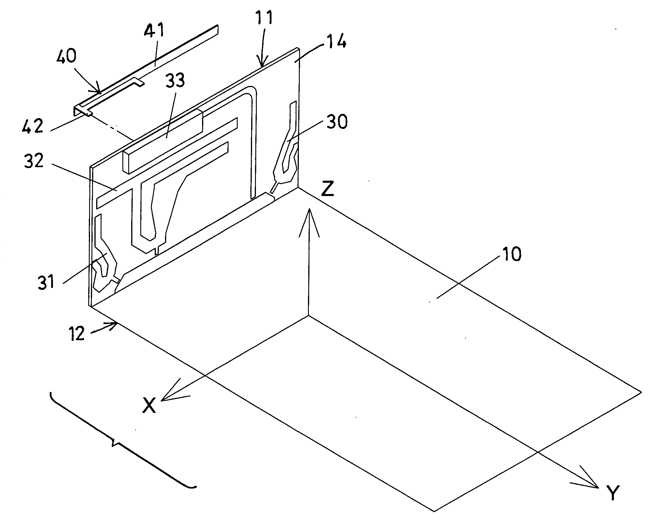
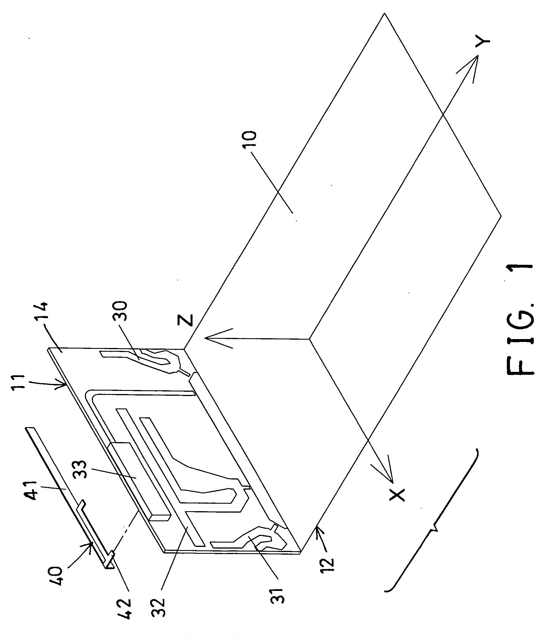
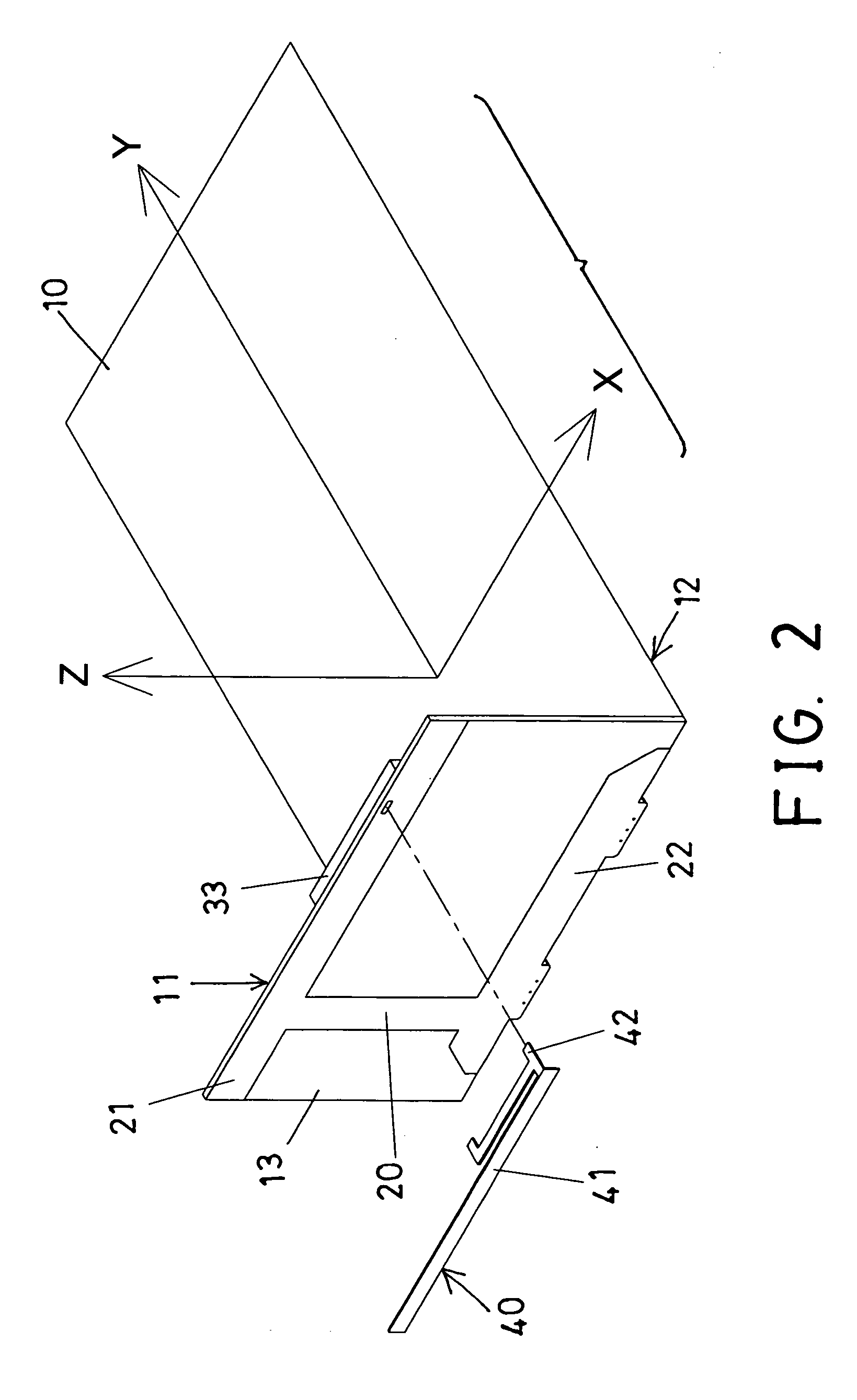
[0028]Referring to the drawings, and initially to FIGS. 1-3, an antenna assembly in accordance with the present invention comprises a circuit board or earth plate or substrate 10, and another substrate or circuit board 11 attached to or extended from one side or one end 12 of the substrate 10, and inclined or perpendicular to the substrate 10, the circuit board 11 includes a conductive member 20 provided or attached to or applied onto one side 13 of the circuit board 11 and having one or more (such as two) ground strips 21, 22 extended from the two ends of the conductive member 20 respectively for forming an I-shaped construction or conductive member 20.

[0029]As shown in FIG. 1, the circuit board 11 includes one or more (such as two) antenna devices 30, 31 provided or attached to or applied onto the other side 14 of the circuit board 11, and the antenna devices 30, 31 may be selected from various antenna devices, such as the 2.4 GHz and 5 GHz double frequency antenna devices, and in...


PUM


Abstract

An antenna assembly includes a circuit board, a substrate extended from one side of the circuit board, a conductive member provided the other side of the circuit board, and a GPS antenna connected to the conductive member and arranged opposite to the second side of the substrate, one or more antenna devices and a GSM antenna are disposed on the circuit board and arranged opposite to the GPS antenna for preventing the GPS antenna and the antenna devices and the GSM antenna from being interfered or affected by each other and for allowing the antenna assembly to suitably transmit and receive the signals.

Description

BACKGROUND OF THE INVENTION[0001]1. Field of the Invention[0002]The present invention relates to an antenna assembly, and more particularly to a multiple frequency antenna assembly including a structure for allowing the antenna assembly to suitably transmit and receive the signals and for increasing the gain of the antenna assembly.[0003]2. Description of the Prior Art[0004]Typical antenna devices comprise one or more antenna conductors or conductive branches each having one or more feeds extended therefrom, and the conductive branches are in adjacent, spaced-apart relationship for transmitting or receiving waves or signals and for allowing the radiators to transmit or to receive waves or signals or different resonant frequencies.[0005]For example, U.S. Pat. No. 6,529,749 to Hayes et al., and U.S. Pat. No. 6,542,126 to Bahr et al. disclose two of the typical compact antenna devices each comprising one or more antenna conductors or conductive branches provided for use within wireless...

Claims


Application Information

Patent Timeline
IPC IPC(8): H01Q21/00H01Q1/38
CPCH01Q1/52H01Q5/371H01Q21/28H01Q9/42
Inventor WU, HUEI CHI
Owner JOYMAX ELECTRONICS CO LTD
Why Eureka
Try Eureka