Compact planar antenna assembly

a technology of antenna assembly and antenna body, which is applied in the direction of resonant antenna, elongated active element feed, and differential interacting antenna combinations, etc., can solve the problems of increasing the manufacturing cost complicated manufacturing processes of the typical antenna assembly, so as to increase the gain of the antenna assembly and reduce the volume or the size or the dimension of the antenna assembly.

Inactive Publication Date: 2010-01-07
JOYMAX ELECTRONICS CO LTD
View PDF4 Cites 7 Cited by
  • Summary
  • Abstract
  • Description
  • Claims
  • Application Information

AI Technical Summary

Benefits of technology

[0010]The primary objective of the present invention is to provide an antenna assembly including two opposite antenna devices for suitably decreasing the volume or the size or the dimension of the antenna assembly and for increasing the gain of the antenna assembly.
[0011]In accordance with one aspect of the invention, there is provided an antenna assembly comprising a substrate including a feed line, and an antenna device including two first radiators disposed on the substrate and electrically coupled to the feed line, and the first radiators being disposed at a distance from each other and each including a middle portion, and two second radiators disposed on the substrate and electrically coupled to the middle portions of the first radiators respectively for suitably decreasing the volume or the size or the dimension of the antenna assembly and for increasing the gain of the antenna assembly.
[0014]A second antenna device may further be provided and include two third radiators disposed on the substrate and electrically coupled to the feed line for further increasing the gain of the antenna assembly. It is preferable that the second antenna device include a structure opposite to that of the first antenna device in a mirror image.

Problems solved by technology

However, the two antenna devices should be disposed on or applied to the two opposite sides of the circuit board such that the manufacturing processes for the typical antenna assembly will be complicated and such that the manufacturing cost of the typical antenna assembly will be increased.

Method used


Image

  • Compact planar antenna assembly
  • Compact planar antenna assembly
  • Compact planar antenna assembly

Examples


Embodiment Construction

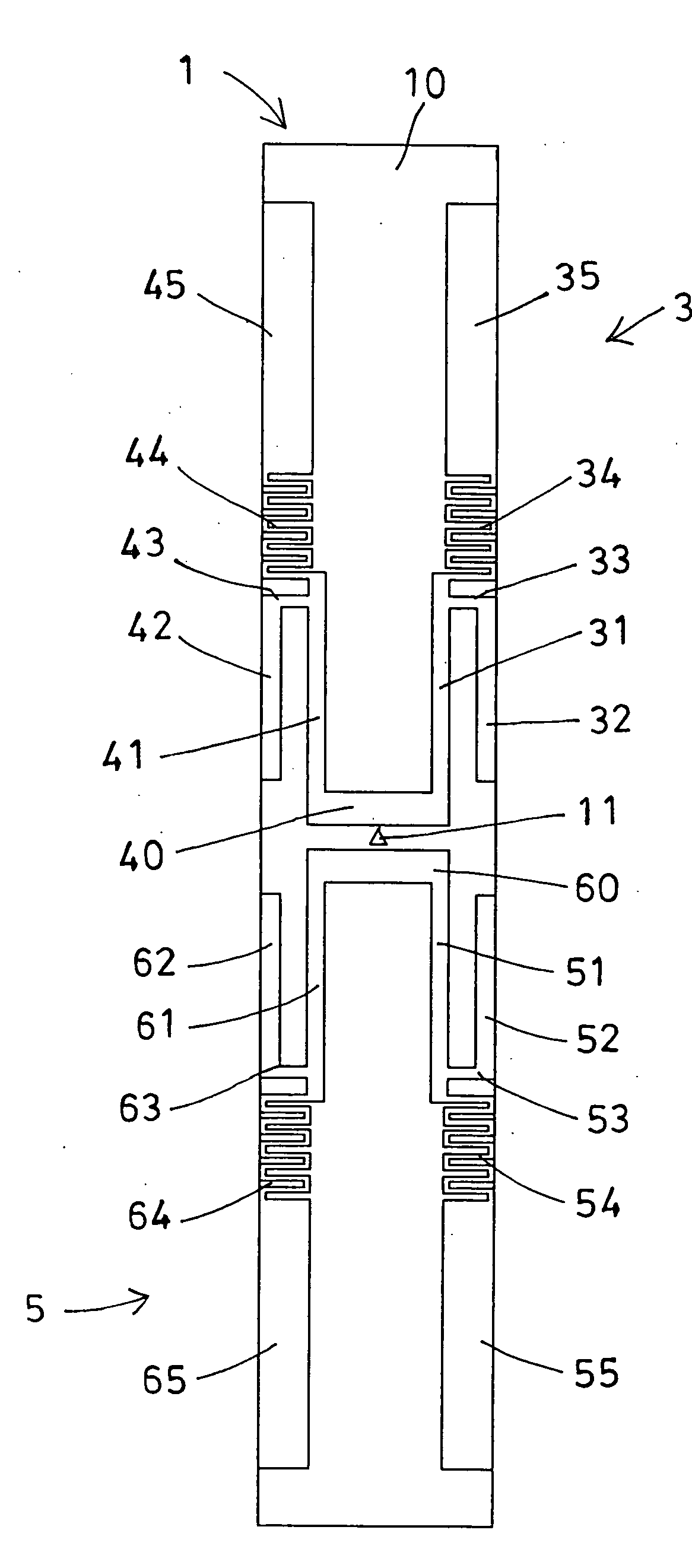
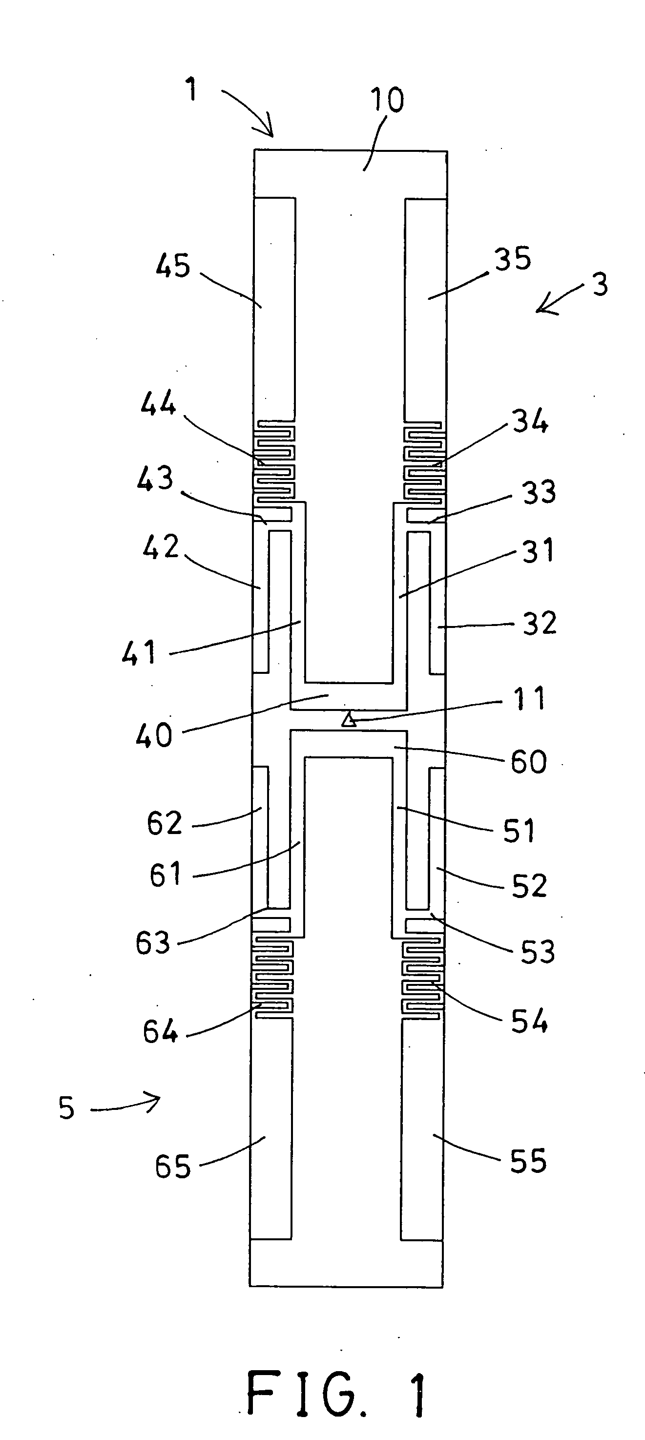
[0029]Referring to the drawings, and initially to FIG. 1, an antenna assembly 1 in accordance with the present invention comprises a printed circuit board or earth plate or substrate 10 including a feed line 11 provided or attached to the middle portion of the substrate 10 for transmitting or receiving waves or signals, and two antenna devices 3, 5 attached to or disposed on the same side or the upper portion of the substrate 10, but disposed on the two opposite ends of the substrate 10, and also disposed on the two opposite ends of the feed line 11 and electrically coupled to the feed line 11. It is preferable that the antenna devices 3, 5 include a structure opposite to each other in a mirror image.

[0030]For example, one of the antenna devices 3 includes two antenna members or radiators 31, 41 attached to or disposed on the substrate 10, and arranged side by side with each other, and coupled together with a coupling member 40 which is then electrically coupled to the feed line 11,...


PUM


Abstract

An antenna assembly includes a substrate having a feed line, and an antenna device having two inner radiators electrically coupled to the feed line and disposed at a distance from each other, and two outer radiators electrically coupled to the middle portions of the inner radiators for decreasing the dimension of the antenna assembly and for increasing the gain of the antenna assembly, the inner radiators each include an antenna segment disposed at a distance parallel to the inner radiators and disposed on an outer portion of the inner radiators, the inner radiators are electrically coupled to the outer radiators with a coupling element which includes either a zigzag shape or a wave-shaped structure.

Description

BACKGROUND OF THE INVENTION[0001]1. Field of the Invention[0002]The present invention relates to an antenna assembly, and more particularly to an antenna assembly including two opposite antenna devices for suitably decreasing the volume or the size or the dimension of the antenna assembly and for increasing the gain of the antenna assembly.[0003]2. Description of the Prior Art[0004]Typical antenna devices comprise one or more printed planar radiating elements applied or disposed on an earth plate or a printed circuit board or a substrate by painting or printing processes, and a ground plane positioned on one or both sides of the substrate, for transmitting or receiving waves or signals and for allowing the radiators to transmit or to receive waves or signals or different resonant frequencies.[0005]For example, U.S. Pat. No. 6,664,926 to Zinanti et al. discloses one of the typical compact antenna devices comprising a radiating element in the shape of a right triangle and formed on a ...

Claims


Application Information

Patent Timeline
Patent Type & Authority Applications(United States)
IPC IPC(8): H01Q9/04
CPCH01Q9/30H01Q21/29H01Q21/062
Inventor WAN, TZE CHUNG
Owner JOYMAX ELECTRONICS CO LTD
Why Eureka
Try Eureka