Automatic gain controller

Inactive Publication Date: 2007-02-22
SAMSUNG ELECTRONICS CO LTD
View PDF3 Cites 9 Cited by
  • Summary
  • Abstract
  • Description
  • Claims
  • Application Information

AI Technical Summary

Benefits of technology

[0029] If the output signal of the low-pass filter is higher than the output signal of the reference voltage level adjustment unit, the comparison unit may decrease the gain of the variable gain amplifie

Problems solved by technology

However, random offset voltages exist in the operational amplifier due to the mismatching of a manufacturing process.
In fact, there is a problem in that the offset voltage is generally in the range of several tens of mV.
Accordingly, supposing that the offset voltage of the operational amplifier used in the conventional automatic

Method used


Image

  • Automatic gain controller
  • Automatic gain controller
  • Automatic gain controller

Examples


Embodiment Construction

[0047] Certain exemplary embodiments of the present invention will be described in greater detail with reference to the accompanying drawings.

[0048] In the following description, same drawing reference numerals are used for the same elements even in different drawings. The matters defined herein are described at a high-level of abstraction to provide a comprehensive yet clear understanding of the invention. It is also to be noted that it will be apparent to those ordinarily skilled in the art that the present invention is not limited to the description of the exemplary embodiments provided herein.

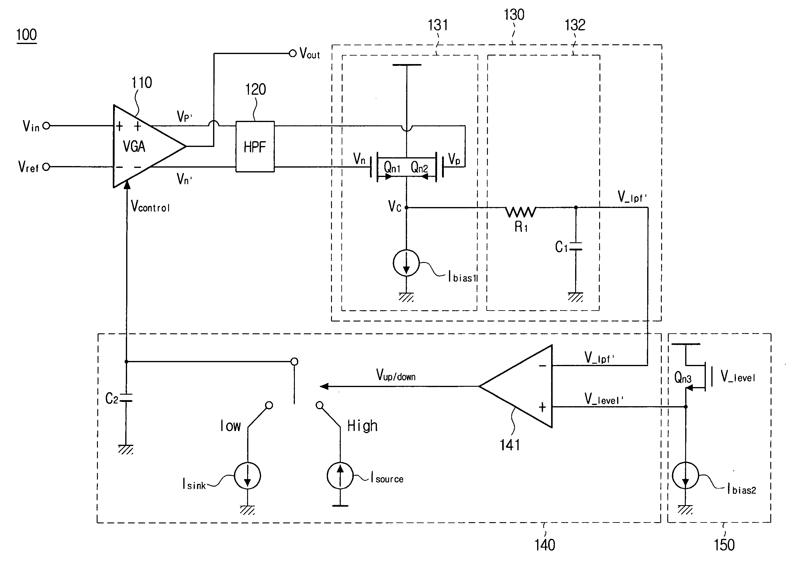
[0049]FIG. 7 is a circuit diagram of an automatic gain controller according to an exemplary embodiment of the present invention. FIGS. 8A through 8G are views illustrating signal waveforms appearing at respective points of the automatic gain controller, as shown in FIG. 7.

[0050] Referring to FIG. 7, an automatic gain controller 100 according to the present invention includes a variable g...


PUM


Abstract

An automatic gain controller includes a variable gain amplifier for amplifying an input signal having a specified DC level on the basis of the DC level, and outputting a first differential signal having a specified gain α, a second differential signal having a 180° phase difference from the first differential signal, and an output signal obtained by subtracting the second differential signal from the first differential signal; a full-wave-rectifying unit for full-wave-rectifying the first differential signal and the second differential signal; a low-pass filter for extracting the DC component from the output signal of the full-wave-rectifying unit and outputting the extracted DC component; a reference voltage level adjustment unit for adjusting a DC level of a reference voltage; and a comparison unit for comparing the output signal of the low-pass filter with the output signal of the reference voltage level adjustment unit to adjust a gain of the variable gain amplifier.

Description

[0001] This application claims priority from Korean Patent Application No. 2005-76855, filed on Aug. 22, 2005, the entire content of which is incorporated herein by reference. BACKGROUND OF THE INVENTION [0002] 1. Field of the Invention [0003] The invention relates to an automatic gain controller. More particularly, the present invention relates to an automatic gain controller that can output an input signal with its amplitude maintained constant, without using an operational amplifier for shifting the direct current (DC) level of the output signal. [0004] 2. Description of the Related Art [0005] An optical disk may be classified into a write-once disk such as a CD-ROM and a DVD-ROM, and a rewritable disk such as a CD-RW, a DVD-RW, and a DVD-RAM. The rewritable disk cannot generate a clock signal from a reproduced signal, unlike an existing read-only disk. Accordingly, grooves of the disk on which information is recorded are wobbled for a predetermined period, and a clock signal req...

Claims


Application Information

Patent Timeline
IPC IPC(8): H03G3/20
CPCG11B20/10009G11B20/10027H03G3/3036H03G3/3084G11B7/09G11B20/10
Inventor KWON, DAE-HOONLEE, JEONG-WON
Owner SAMSUNG ELECTRONICS CO LTD
Why Eureka
Try Eureka