Disconnectable chain connector

a chain connector and disconnection technology, applied in the direction of special purpose vessels, vessel parts, vessel construction, etc., can solve the problems of ease of further maintenance operation

Active Publication Date: 2014-04-01
SINGLE BUOY MOORINGS INC
View PDF23 Cites 12 Cited by
  • Summary
  • Abstract
  • Description
  • Claims
  • Application Information

AI Technical Summary

Benefits of technology

[0008]The invention provides a mooring leg connector for use with a mooring leg extending up from the sea floor to connect a floating structure to be moored to the seabed wherein disconnection and connection of the mooring leg is done by pulling in and out the connector elongated body extending in the mooring leg direction, the connector having a latch mechanism for fixation of the mooring leg to the floating structure to be moored and preventing movement in the direction of the seabed, and a flexible part with a double articulation axis located at the bottom of the connector body above the attachment member, the connector being received in a housing which is fixed to a part of the structure to be moored, the latch mechanism comprising a system of cam or guiding means and followers or orientation pins between the rod of the connector and the housing. Another object of the invention is to provide a mooring leg connector for use with a mooring leg that has an upper portion with an axis, where the chain extends up from the sea floor, to connect the bottom of a turret integrated into or attached to the hull of a floating structure to be moored to the seabed, said connector having an elongated body extending in the mooring leg direction and a latch mechanism for fixation of the mooring leg to the floating structure to be moored and preventing movement in the direction of the seabed, the connector being received in a housing which is integral (or at least rigidly connected) to a part of the structure to be moored, wherein the connector comprises a flexible part with a double articulation axis located at the bottom of the connector body above the attachment member and wherein the latch mechanism is a system made by cam (or guiding member) and followers (or orientation pins) between the rod of the connector and the housing.

Problems solved by technology

The solution proposed aims at securing tethers to a sea floor receptacle mechanism, these solutions are not ideal as inspection of the articulation in dry environment are not possible without disconnecting, further maintenance operation are not eased.

Method used


Image

  • Disconnectable chain connector
  • Disconnectable chain connector
  • Disconnectable chain connector

Examples


Embodiment Construction

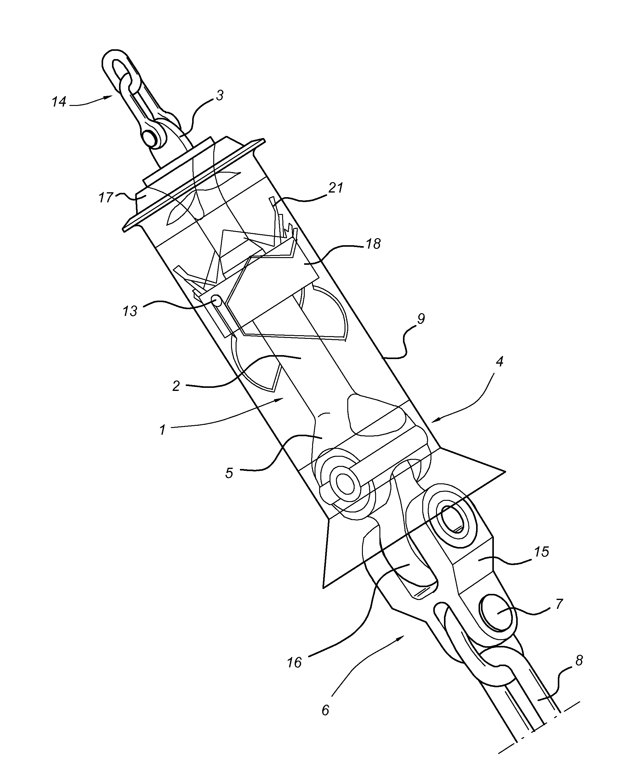
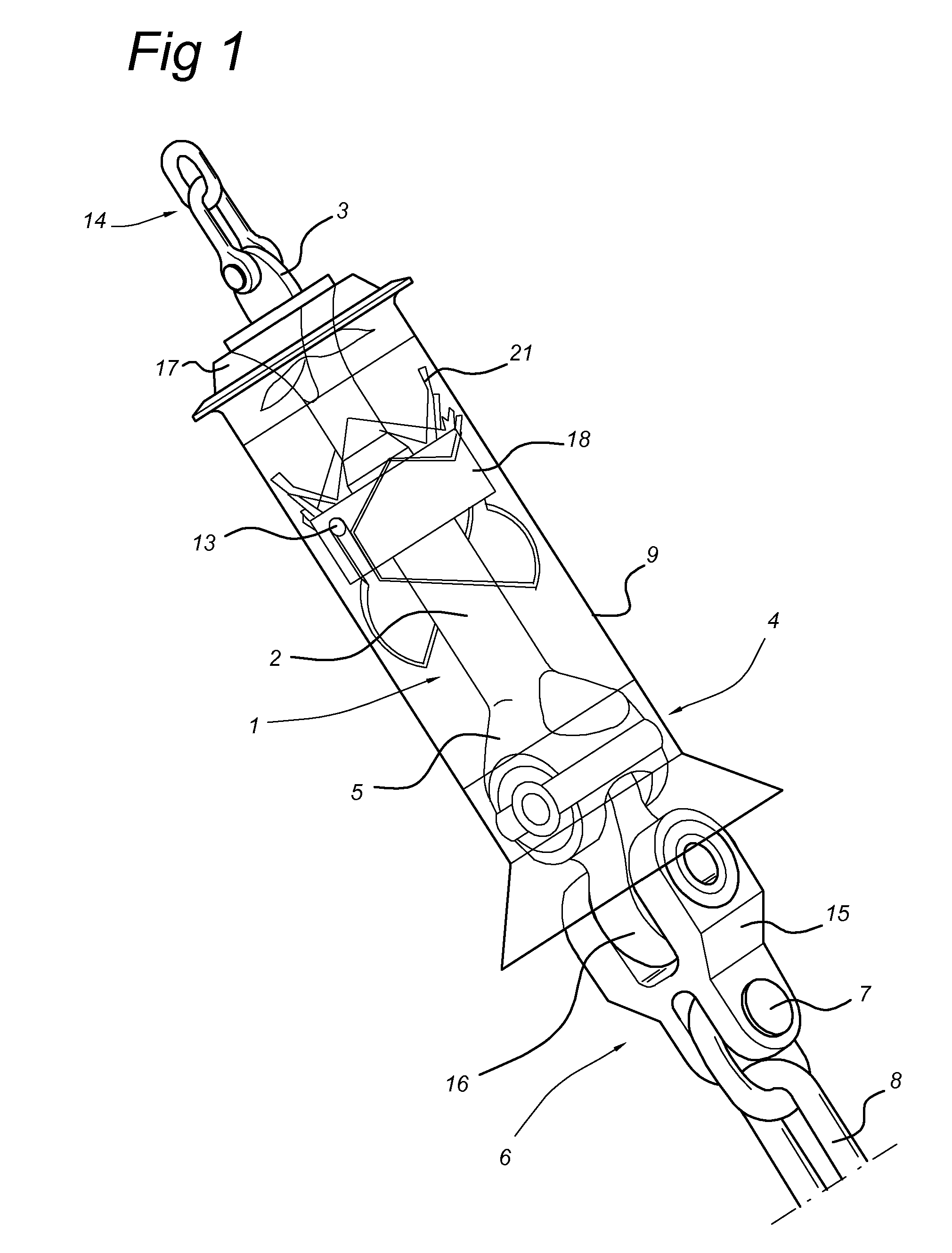
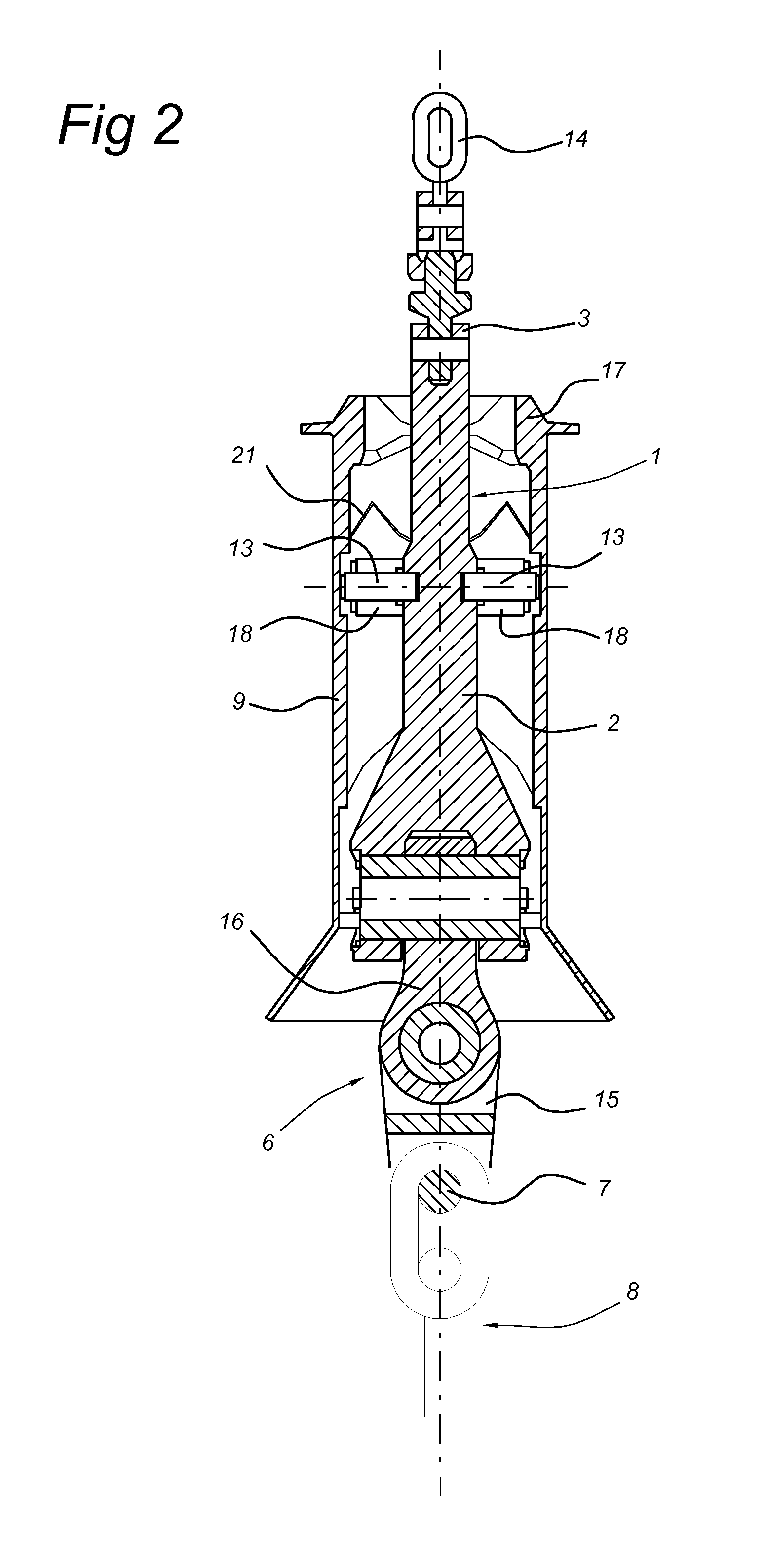
[0030]FIG. 1 shows a perspective view of the chain connector according to the present invention and FIG. 2 shows cross-sectional view of the chain connector according to the present invention. In these figures, it appears clearly that the connector has an elongated body 1, received in a housing 9, with a broad head part 3 for attaching the pull-in chain 14, a tubular shaped middle part or rod 2 getting larger towards the bottom part 4, said bottom part comprising an enlargement 5 for engaging the flexible lower part 6 with a double articulation. The double articulation allows pivoting of the upper link of the mooring leg as would a unijoint. According to the present invention, the articulated part is located at the bottom of the connector body above the attachment member 7, where the mooring leg 8 is attached. The part 15 (or roll body) of the flexible lower part 6‘rolls’ with regard to part 16 (or pitch body) which ‘pitches’ with respect to the rod 2; the latter is supported by the...


PUM


Abstract

A mooring leg connector for use with a mooring leg extending up from the sea floor to connect a floating structure to be moored to the seabed wherein disconnection and connection of the mooring leg is done by pulling in and out a connector elongated body extending in the mooring leg direction. The connector has a latch mechanism for fixation of the mooring leg to the floating structure to be moored and preventing movement in the direction of the seabed, and a flexible part with a double articulation axis located at the bottom of the connector body above the attachment member, the connector body being received in a housing which is fixed to a part of the structure to be moored, wherein the latch mechanism includes guiding elements and followers or orientation pins between the body of the connector and the housing.

Description

FIELD OF THE INVENTION[0001]The present invention relates to a mooring leg connector for use with a mooring leg extending up from the sea floor to connect a floating structure to be moored to the seabed wherein disconnection and connection of the mooring leg is done by pulling in and out the connector elongated body extending in the mooring leg direction, the connector having a latch mechanism for fixation of the mooring leg to the floating structure to be moored and preventing movement in the direction of the seabed, and a flexible part with a double articulation axis located at the bottom of the connector body above the attachment member, the connector being received in a housing which is fixed to a part of the structure to be moored.[0002]The present invention also relates to methods for locking and unlocking a mooring leg connector to a floating structure to be moored to the seabed, said connector having an elongated body extending in the mooring leg direction and a latch mechan...

Claims


Application Information

Patent Timeline
Patent Type & Authority Patents(United States)
IPC IPC(8): B63B21/00
CPCB63B21/502B63B22/04B63B21/10F16B21/16Y10T403/7066B63B21/18
Inventor BAUDUIN, CHRISTIAN RAYMONDBRAUD, JEANBENOIT, JEAN PIERRE
Owner SINGLE BUOY MOORINGS INC
Why Eureka
Try Eureka