Micro-electromechanical switch protection in series parallel topology

a micro-electromechanical and switch protection technology, applied in the direction of protective switches using micromechanics, circuit-breaking switches, relays, etc., can solve the problems of leakage current, circuit breakers are large in size, circuit breakers include bulky electromechanical switches,

Active Publication Date: 2014-04-01
GENERAL ELECTRIC CO
View PDF30 Cites 7 Cited by
  • Summary
  • Abstract
  • Description
  • Claims
  • Application Information

AI Technical Summary

Problems solved by technology

Traditionally, most conventional circuit breakers include bulky electromechanical switches.
Unfortunately, these conventional circuit breakers are large in size thereby necessitating use of a large force to activate the switching mechanism.
However, since solid-state switches do not create a physical gap between contacts when they are switched into a non-conducting state, they experience leakage current.
However, the arrays of switches open or close asynchronously, resulting in an undesirable magnitude of load current flowing through the switches.
Accordingly, the load current may exceed the current handling capabilities of the switches causing shorting or welding and rendering the switches inoperable.

Method used


Image

  • Micro-electromechanical switch protection in series parallel topology
  • Micro-electromechanical switch protection in series parallel topology
  • Micro-electromechanical switch protection in series parallel topology

Examples


Embodiment Construction

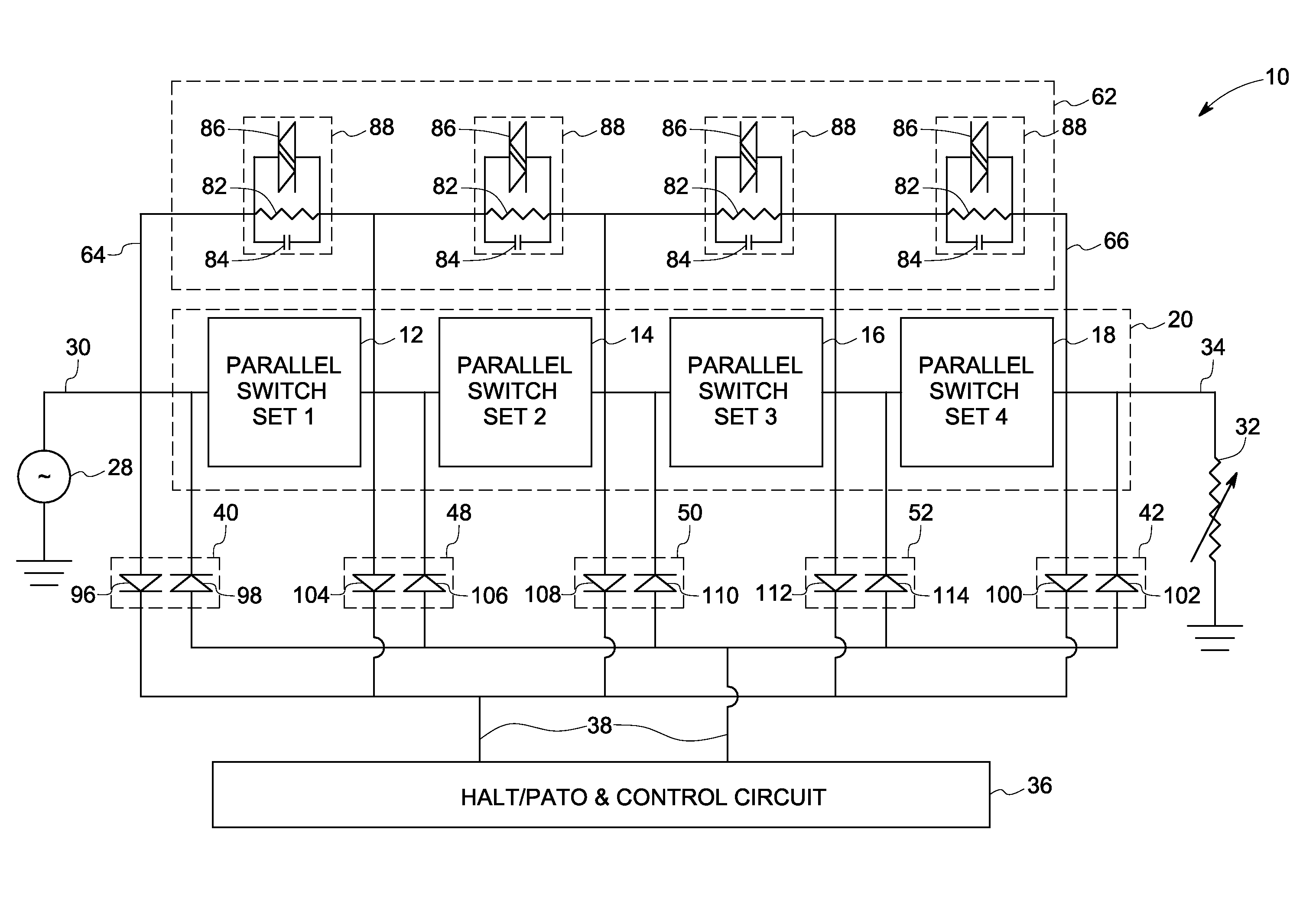
[0012]In accordance with embodiments of the invention, structural and / or operational relationships, as may be used to provide voltage scalability (e.g., to meet a desired voltage rating) in a switching array based on micro-electromechanical systems (MEMS) switches are described herein. Typically, MEMS refer to micron-scale structures that, for example, can integrate a multiplicity of functionally distinct elements, e.g., mechanical elements, electromechanical elements, sensors, actuators, and electronics, on a common substrate through micro-fabrication technology. It is contemplated, however, that many techniques and structures presently available in MEMS devices will be available via nanotechnology-based devices, e.g., structures that may be smaller than 100 nanometers in size. Further, it will be appreciated that MEMS based switching devices, as referred to herein, may be broadly construed and not limited to nanotechnology based devices or micron-sized devices.

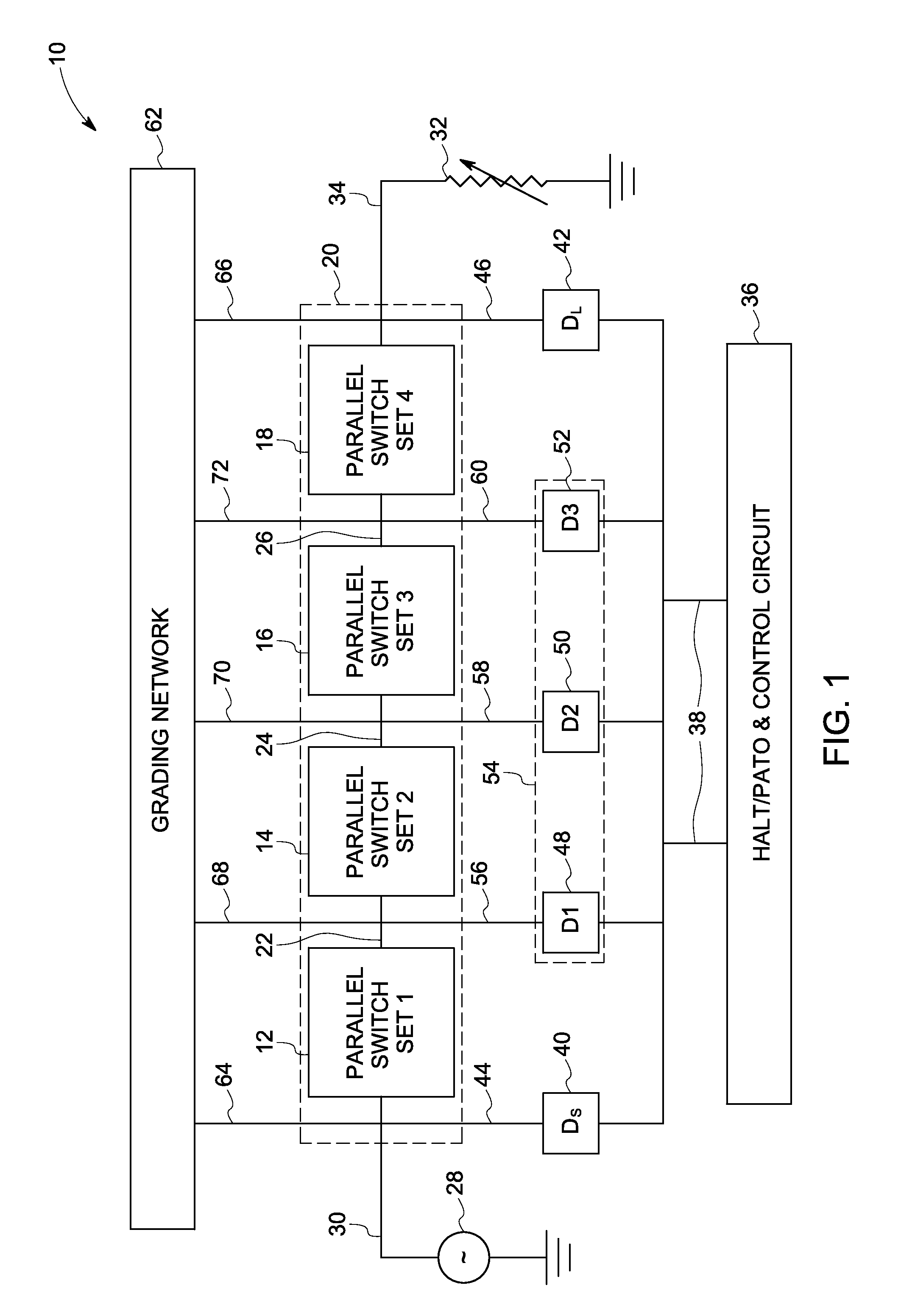
[0013]FIG. 1 is a bl...


PUM


Abstract

An electrical switching device is presented. The electrical switching device includes multiple switch sets coupled in series. Each of the switch sets includes multiple switches coupled in parallel. A control circuit is coupled to the multiple switch sets and configured to control opening and closing of the switches. One or more intermediate diodes are coupled between the control circuit and each point between a respective pair of switch sets.

Description

BACKGROUND[0001]The invention relates generally to protection of switching devices, and more particularly, to protection of micro-electromechanical system based switching devices.[0002]A circuit breaker is an electrical device designed to protect electrical equipment from damage caused by faults in a circuit. Traditionally, most conventional circuit breakers include bulky electromechanical switches. Unfortunately, these conventional circuit breakers are large in size thereby necessitating use of a large force to activate the switching mechanism. Accordingly, to employ electromechanical contactors in power system applications, it may be desirable to protect the contactor from damage by backing it up with a series device that is sufficiently fast acting to interrupt fault currents prior to the contactor opening at all values of current above the interrupting capacity of the contactor.[0003]As an alternative to slow electromechanical switches, fast solid-state switches have been employ...

Claims


Application Information

Patent Timeline
Patent Type & Authority Patents(United States)
IPC IPC(8): H01H9/30H01H73/18
CPCH01H59/0009H01H2071/008H01H71/00
Inventor PREMERLANI, WILLIAM JAMESO'BRIEN, KATHLEEN ANNSCHELENZ, OWEN JANNIS
Owner GENERAL ELECTRIC CO
Why Eureka
Try Eureka