Permanent magnet rotor

a permanent magnet, rotating technology, applied in the direction of magnetic circuit rotating parts, dynamo-electric machines, magnetic circuit shape/form/construction, etc., can solve the problems of poor manufacturability, failure of the rotor, adhesive strength, etc., to achieve good manufacturability and repeatability, simple, convenient, reliable, and good manufacturability.

Inactive Publication Date: 2014-04-08
JOHNSON ELECTRIC SA
View PDF16 Cites 1 Cited by
  • Summary
  • Abstract
  • Description
  • Claims
  • Application Information

AI Technical Summary

Benefits of technology

[0018]Advantages of embodiments of the present invention include that the linker and the magnet is fixed together by means of an elastic clamping structure while the traditional way of fixation by means of binder is avoided. The way of connection is simple, convenient, reliable and has good manufacturability and repeatability; the inner diameter of the magnet can have a relatively large tolerance because teeth formed on the surface of the positioning pins arranged on the linker press against the inner surface of magnet; and balance pins arranged on the linker can be used for dynamic balancing of the rotor.

Problems solved by technology

1) With changes in temperature and prolongation of the duration of usage, the binder is easily aged and may lose its adhesive strength, thereby resulting in failure of the rotor.
2) The manufacturability is poor. A paste binder is difficult to apply evenly, in production which easily results in the magnet being eccentrically mounted to the rotor core, thereby generating one extra factor affecting the imbalance of the rotor.

Method used


Image

  • Permanent magnet rotor
  • Permanent magnet rotor
  • Permanent magnet rotor

Examples


Embodiment Construction

[0025]The technical problem to be solved, the technical solution and the beneficial effects of the present invention are best understood from the following detailed description with reference to the accompanying figures and embodiments. It is to be understood that the specific embodiments described here are merely examples to explain the invention and are not intended to limit the scope of the present invention.

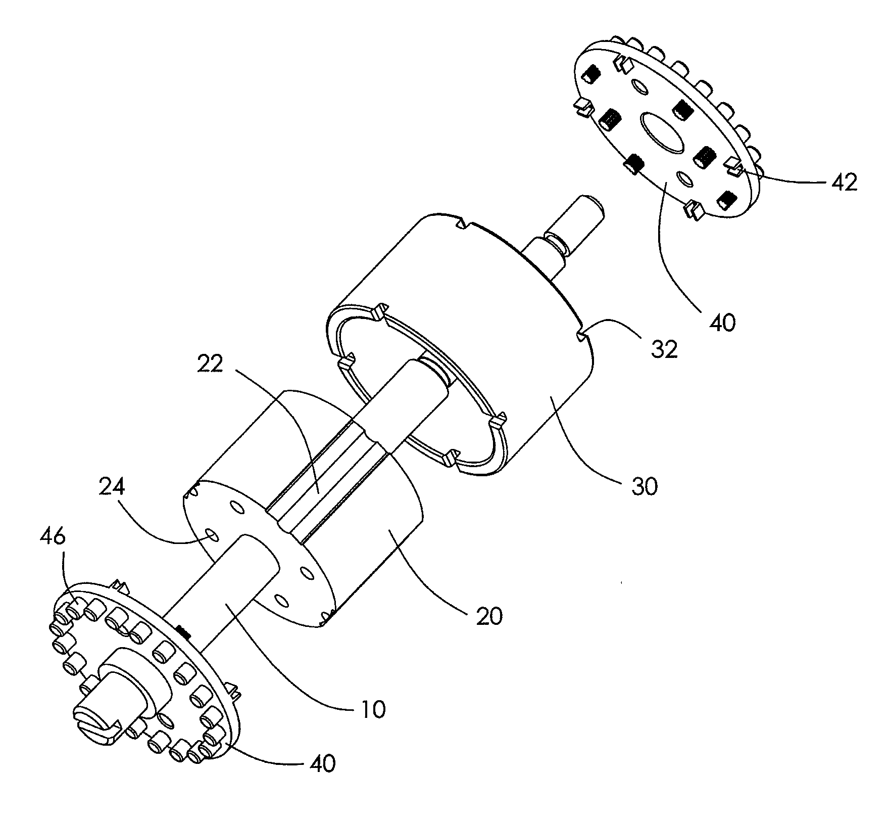
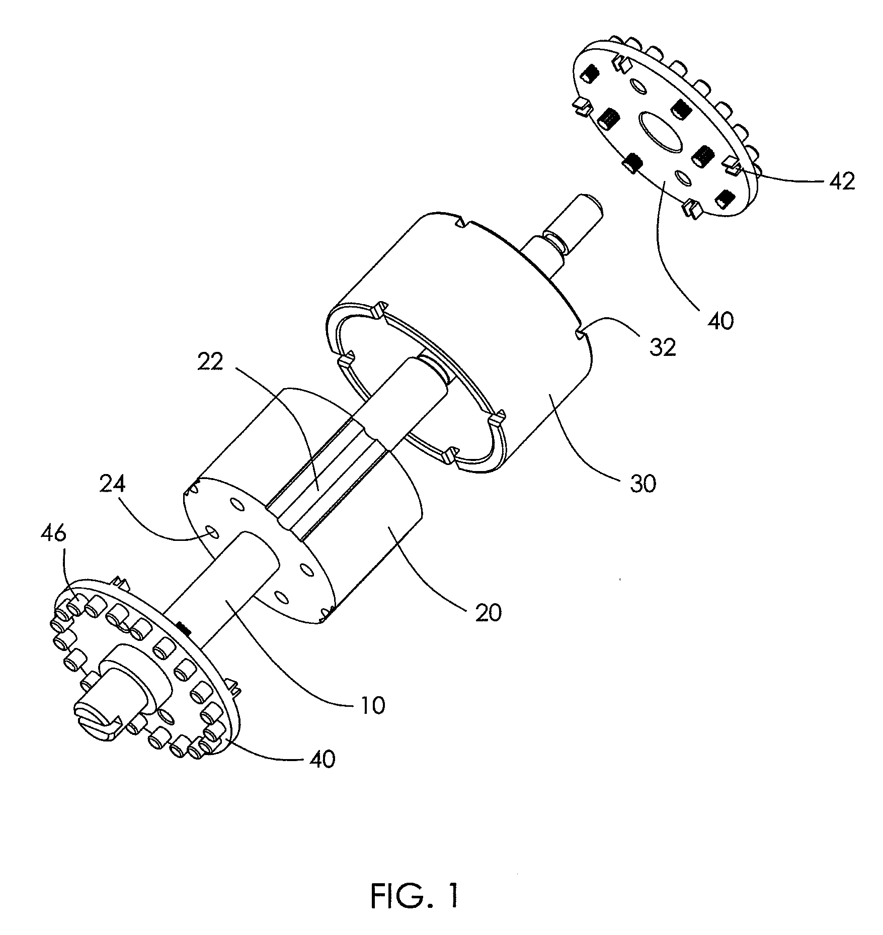
[0026]Referring to FIG. 1, a motor rotor according to the preferred embodiment of the present invention comprises a shaft 10, a rotor core 20 fixed to the shaft 10, a magnet 30 disposed around the core 20, and a linker 40 fixed to one end of the core 20. An elastic clamping structure is arranged between the linker 40 and the magnet 30 such that rotational torque of the magnet 30 is transferred to the shaft 10 via the linker 40 and the core 20.

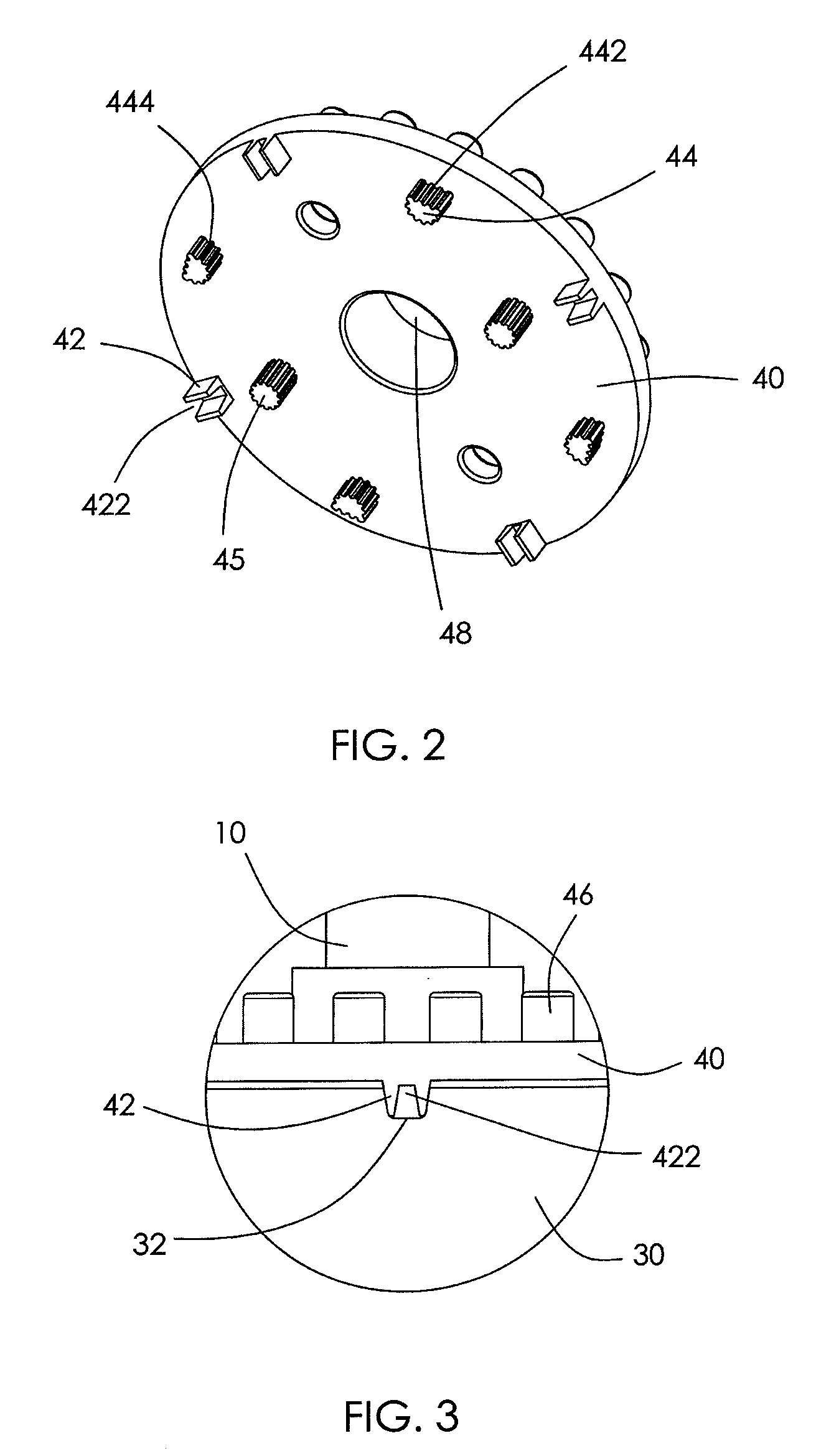
[0027]Referring to FIG. 2 and FIG. 3, optionally, recesses 32 are formed on one end of the magnet 30 proximate the linker 40. Elastic p...


PUM


Abstract

A permanent magnet rotor including a shaft, a rotor core fixed to the shaft, a magnet disposed around the core, and a linker fixed relative to the shaft and located at one end of the core. An elastic clamping structure is arranged between the linker and the magnet such that rotational torque of the magnet is transferred to the shaft via the linker.

Description

CROSS REFERENCE TO RELATED APPLICATIONS[0001]This non-provisional patent application claims priority under 35 U.S.C. §119(a) from Patent Application No. 200910107313.6 filed in The People's Republic of China on May 12, 2009.FIELD OF THE INVENTION[0002]The invention relates to the electric motors, and in particular, to a permanent magnet rotor of a brushless DC motor.BACKGROUND OF THE INVENTION[0003]A permanent magnet brushless DC motor usually comprises a shaft, a rotor core fixed to the shaft and one or more magnets disposed around the core. In the prior art, the magnet and the rotor core are usually attached by a binder such as an epoxy resin. The binder is used as a torque transfer structure between the magnet and the rotor core for transferring the rotational torque of the magnet to the shaft, thereby driving the shaft.[0004]However, adhesion by means of a binder has following disadvantages:[0005]1) With changes in temperature and prolongation of the duration of usage, the binde...

Claims


Application Information

Patent Timeline
Patent Type & Authority Patents(United States)
IPC IPC(8): H02K1/27H02K5/24H02K21/14H02K1/30H02K21/12H02K1/28
CPCH02K1/30H02K1/276H02K5/24H02K21/14H02K1/28H02K1/278
Inventor LAU, JAMES CHING SIKYANG, JUNHE, WAN MEI
Owner JOHNSON ELECTRIC SA
Why Eureka
Try Eureka