Adjustable absorber designs for implantable device

a technology of absorber and absorber, which is applied in the field of adjustable absorber design for implantable devices, can solve the problems of chondroprotective treatment, arthroplasty procedures are characterized by relatively long recovery time, and high invasive procedures, and achieve the effect of facilitating translation through the skin and preventing accidental unlocking and/or translation

Inactive Publication Date: 2014-04-29
MOXIMED INC
View PDF184 Cites 49 Cited by
  • Summary
  • Abstract
  • Description
  • Claims
  • Application Information

AI Technical Summary

Benefits of technology

[0016]Yet another embodiment of an energy absorbing device includes an arbor having a first shaft and a second shaft, the first and second shafts each having a lumen extending at least partially through each of the first and second shafts. A collar is slidably engaged to the first and second shafts, and the collar is configured to lock into a position along the lengths of the first and second shafts. There is also a piston base having a first piston and a second piston extending from the piston base, with the first and second pistons configured to slide within the lumens of the first and second arbor shafts, respectively. Again, the anchor base can be equipped with through holes in communication with the lumen which received the piston shafts. A first spring is disposed over the first arbor shaft between the collar and the piston base arbor, and a second spring is disposed over the second arbor shaft between the collar and the piston base. Adjusting the position of the collar over the first and second arbor shafts changes the compression of the first and second springs, which alters the load manipulating characteristics of the energy absorbing device.
[0020]Adjustments may be done through or over the skin of a patient. In some embodiments, an audible sound such as a click is created by the collar or adjustment assembly when it is unlocked or locked to provide feedback to the physician. Also, audible sounds or tactile feedback can be provided to the physician as the collar or adjustment assembly is translated along the length of the shaft. Such feedback can be incorporated both into unlocking the energy absorbing device as well as for translating components of the device to new positions. Structure can be further incorporated into the implanted system to prevent accidental unlocking and / or translation as well as to facilitate translation through the skin. In the latter regard, the motion or placement of members defining the target joint and secondary structures such as a secondary compression spring can be utilized.

Problems solved by technology

Such procedures are a last resort treatment as they are highly invasive and require substantial periods of recovery.
As with joint replacement, these other arthroplasty procedures are also characterized by relatively long recovery times and their highly invasive procedures.
Because of this, none of these currently available therapies are chondro-protective.
A misalignment due to injury or disease in a joint relative to the direction of load can result in an imbalance of forces and pain in the affected joint.
However, HTO does not address ligamentous instability—only mechanical alignment.
HTO is associated with good early results, but results deteriorate over time.
If the load falls below the nominal range for extended periods of time, bone and cartilage can become softer and weaker (atrophy).
Finally, if the load rises too high, then abrupt failure of bone, cartilage and other tissues can result.
Accordingly, it has been concluded that the treatment of osteoarthritis and other bone and cartilage conditions is severely hampered when a surgeon is not able to precisely control and prescribe the levels of joint load.
A number of these approaches have had some success in alleviating pain but have ultimately been unsuccessful due to lack of patient compliance or the inability of the devices to facilitate and support the natural motion and function of the diseased joint.
The mechanical approaches to treating osteoarthritis have not taken this into account and have consequently had limited success.
Prior approaches to treating osteoarthritis have also failed to account for all of the basic functions of the various structures of a joint in combination with its unique movement.
Prior devices designed to reduce the load transferred by the natural joint typically incorporate relatively rigid constructs that are incompressible.
Device constructs which are relatively rigid do not allow substantial energy storage as the forces acting on them do not produce substantial deformations—do not act through substantial distances—within them.

Method used


Image

  • Adjustable absorber designs for implantable device
  • Adjustable absorber designs for implantable device
  • Adjustable absorber designs for implantable device

Examples


Embodiment Construction

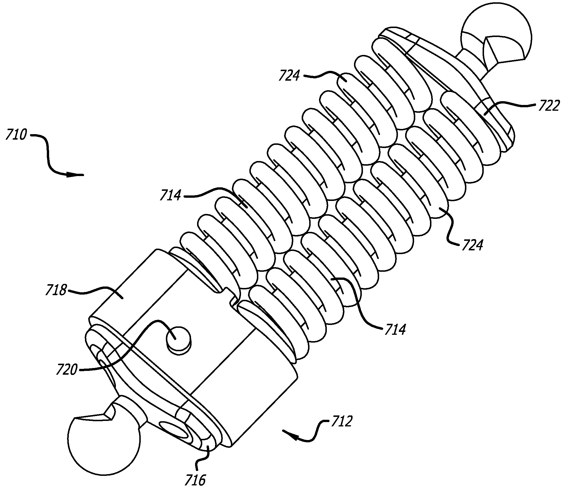
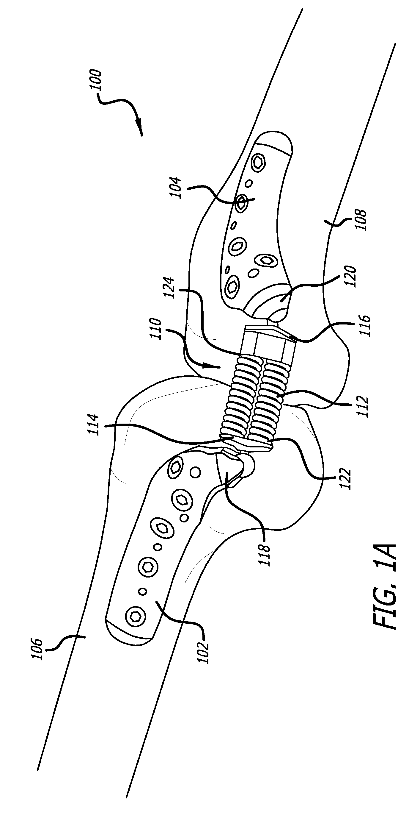
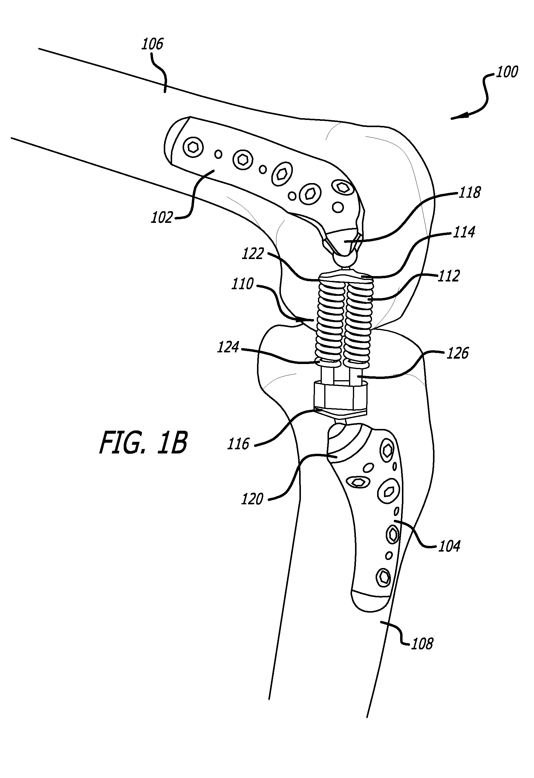
[0101]Referring now to the drawings, which are provided by way of example and not limitation, the disclosed embodiments are directed towards apparatus and methods for treating the knee joint. However, these embodiments may also be used in treating other body joints, and to alleviate pain associated with the function of diseased or misaligned members forming a body joint without limiting the range of motion of the joint. The embodiments described below relate to apparatuses and methods for adjusting the amount of load an energy absorbing device can manipulate. Some embodiments include an energy absorbing device including a dual spring member and other embodiments include the use of a single spring member.

[0102]Certain of the embodiments include energy absorbing devices designed to minimize and complement the dampening effect and energy absorption provided by the anatomy of the body, such as that found at a body joint. It has been postulated that to minimize pain, load manipulation or...


PUM


Abstract

A system for manipulating energy transferred by members defining a joint. The system includes a first attachment structure configured to be attached to a first member of the joint and a second attachment structure configured to be attached to a second member of the joint. There is also an adjustable energy absorbing device attached to the first attachment structure and second attachment structure, wherein adjusting the energy absorbing device changes the load manipulating characteristics of the energy absorbing device.

Description

CROSS-REFERENCES TO RELATED APPLICATIONS[0001]This application is a continuation-in-part of U.S. application Ser. No. 11 / 743,097, filed May 1, 2007, a continuation-in-part of U.S. application Ser. No. 11 / 743,605, filed May 2, 2007, a continuation-in-part of U.S. application Ser. No. 11 / 775,139, filed Jul. 9, 2007, a continuation-in-part of U.S. application Ser. No. 11 / 775,149, filed Jul. 9, 2007 and a continuation-in-part of U.S. application Ser. No. 11 / 775,145, filed Jul. 9, 2007, the entire disclosures of which are expressly incorporated herein by reference.BACKGROUND[0002]Joint replacement is one of the most common and successful operations in modern orthopaedic surgery. It consists of replacing painful, arthritic, worn or diseased parts of a joint with artificial surfaces shaped in such a way as to allow joint movement. Osteoarthritis is a common diagnosis leading to joint replacement. Such procedures are a last resort treatment as they are highly invasive and require substantia...

Claims


Application Information

Patent Timeline
Patent Type & Authority Patents(United States)
IPC IPC(8): A61F2/38
CPCA61B17/6425A61B2017/567A61F2002/087A61B17/6491A61F2002/0829A61B2017/606A61F2/0811A61B17/8004A61F2002/0864A61F2002/0888A61F2/08A61B17/68A61F2250/0012
Inventor MAKOWER, JOSHUASLONE, CLINTON N.REGALA, ALAN C.LANDRY, MICHAEL E.TAMMEN, WILLIAM G.
Owner MOXIMED INC
Why Eureka
Try Eureka