Safety lock mechanism for folding knives

a safety lock and folding knife technology, applied in the field of folding knives, can solve the problems of unintended deployment and closure of the knife blade from an open position, and presenting a safety hazard to users, so as to achieve the effect of preventing unintended movement of the knife blad

Active Publication Date: 2011-07-19
KAI US
View PDF38 Cites 46 Cited by
  • Summary
  • Abstract
  • Description
  • Claims
  • Application Information

AI Technical Summary

Benefits of technology

[0006]According to various embodiments, a safety lock mechanism of a folding knife effectively prevents unintended movement of a knife blade from a closed or open position. According to one embodiment, the safety lock mechanism has a lock plate movably coupled to a handle of a knife for movement along a first direction from an engaged position to a disengaged position, the lock plate biased towards the engaged position. A rocker element is movably coupled to the lock plate for movement from a locked position to an unlocked position and is configured to prevent translation of the lock plate to the disengaged position while in the locked position.
[0008]A control button coupled to the rocker element and accessible to a user at an outer side of the handle permits the user to move the rocker element to the unlocked position and the lock plate to the disengaged position to thereby release a blade of the knife.

Problems solved by technology

One difficulty that has been encountered is that the locking mechanism of many knives is prone to inadvertent disengagement of the lock which can lead to unintended deployment of the knife blade from a closed position or unintended closure from an open position.
Such unintended deployment and closure of the knife blade presents a safety hazard to users, particularly in the case of an automatic knife (i.e., switchblade) or a knife having an assisted opening mechanism.

Method used


Image

  • Safety lock mechanism for folding knives
  • Safety lock mechanism for folding knives
  • Safety lock mechanism for folding knives

Examples


Embodiment Construction

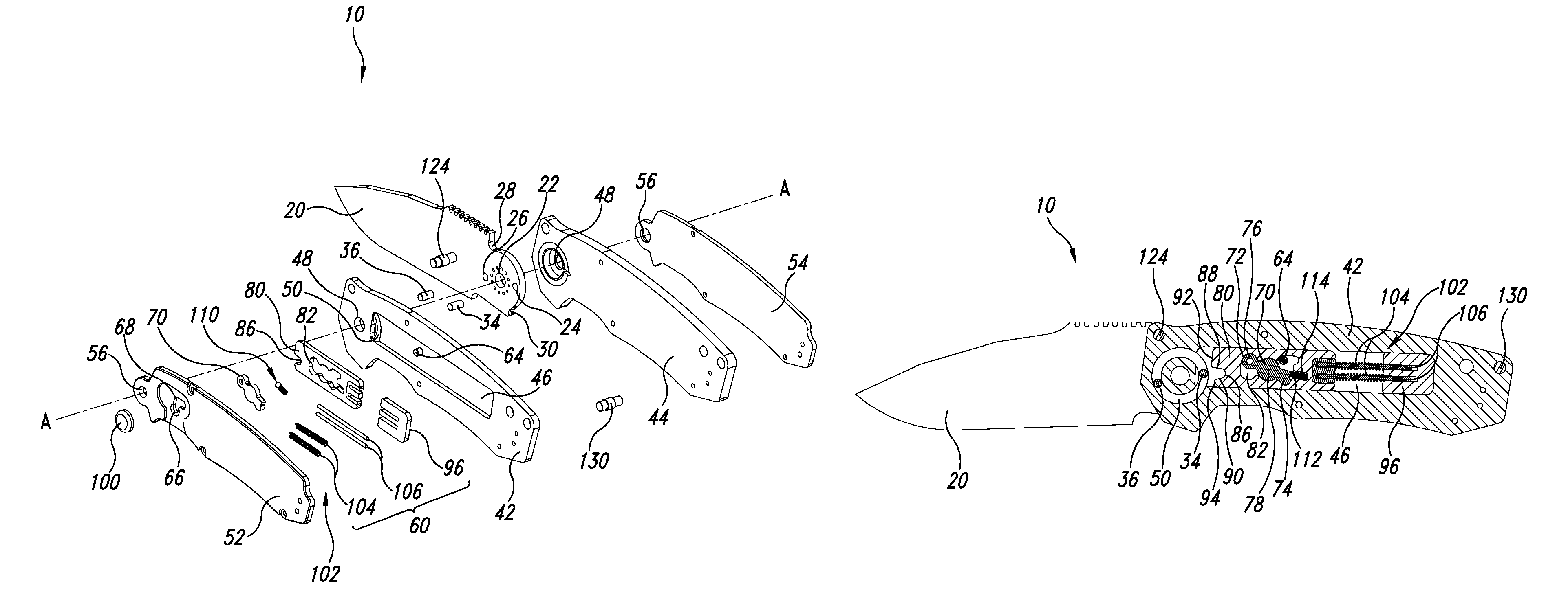
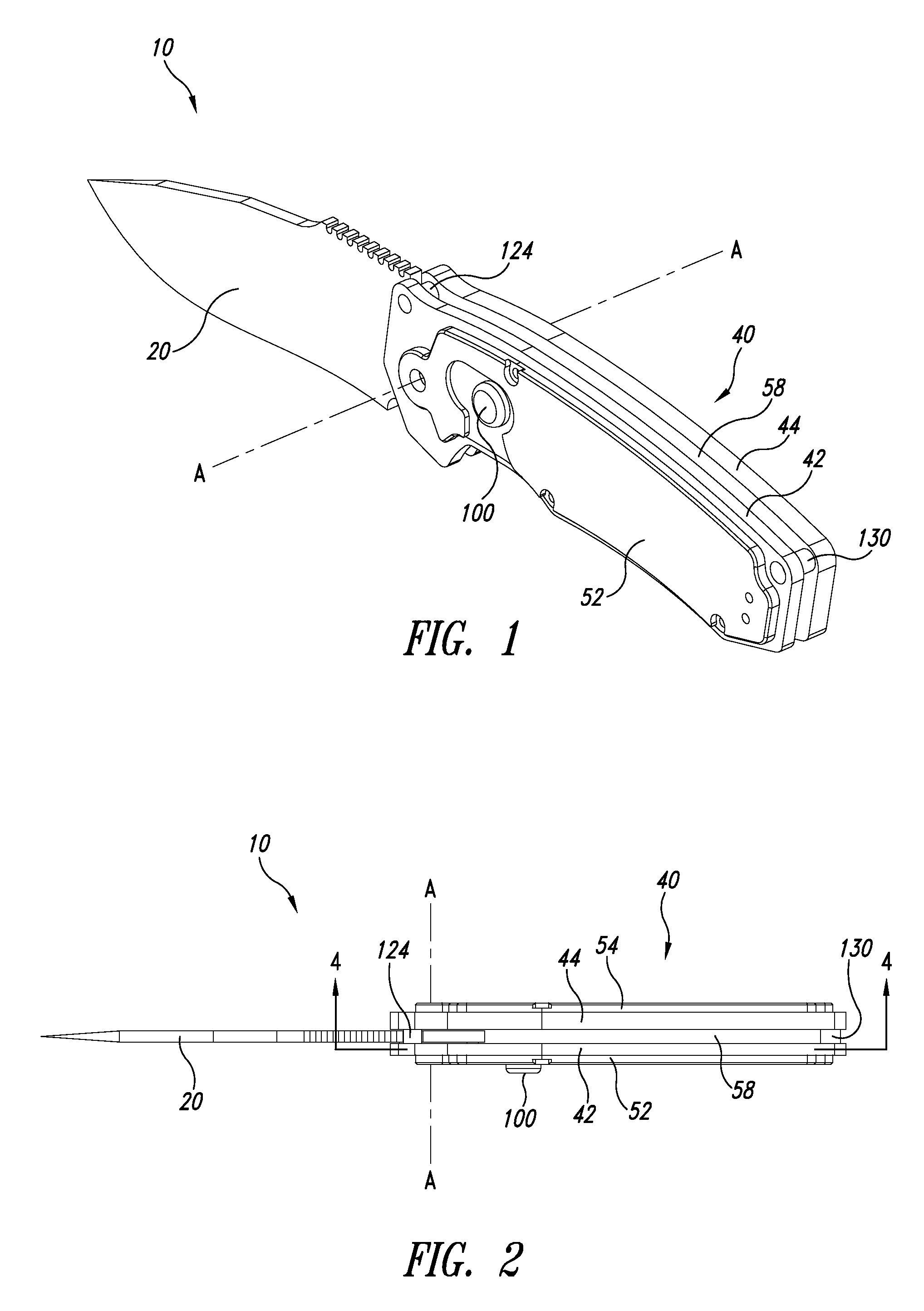
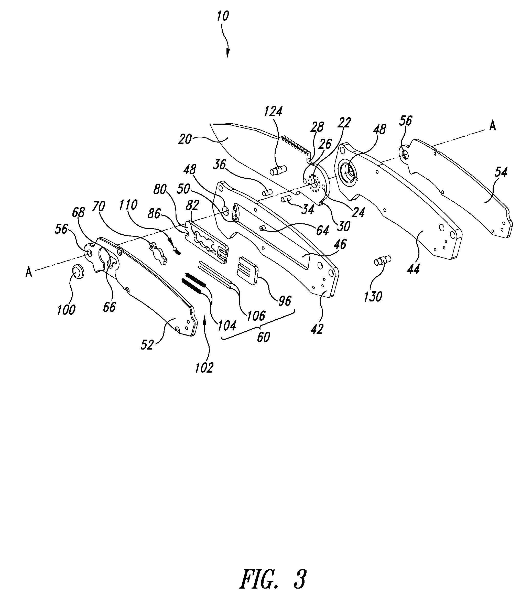
[0016]For the purposes of clarity and ease of comprehension, directional terms such as, for example, top, bottom, right, and left may be used in describing embodiments, and will be with reference to elements as they appear on the figures. Where elements are described using terms such as inner or outer, this is with respect to a central plane of the knife, i.e., a plane that lies parallel to, and substantially centered between, the first and second frame members. Thus, a side of an element that lies closer to that center plane than another side of the element may be described as the inner side of the element.

[0017]Elements that are, in the illustrated embodiment, substantially identical will be identified by identical reference numbers. Where it is necessary to distinguish between such identical elements in the description, letters will be used. Fasteners, which may be screws, rivets, pins, or other suitable devices such as are well known in the art, are not illustrated for purposes ...


PUM


Abstract

A safety lock mechanism for a folding knife includes a lock plate movably coupled to a handle of the knife for movement along a first direction from an engaged position to a disengaged position, the lock plate biased towards the engaged position. A rocker element is coupled to the lock plate for movement from a locked position to an unlocked position and is configured to prevent translational movement of the lock plate to the disengaged position when the rocker element is in the locked position. A control button coupled to the rocker element allows a user to move the rocker element from the locked position to the unlocked position and to move the lock plate towards the disengaged position to thereby release a blade of the knife.

Description

BACKGROUND[0001]1. Technical Field[0002]This disclosure generally relates to folding knives, and in particular to folding knives having safety lock mechanisms.[0003]2. Description of the Related Art[0004]Folding knives enjoy wide popularity, particularly among sportsmen, campers, hikers, and many others engaged in outdoor activities. Common elements to folding knives include a handle and a blade pivotally connected to an end of the handle so that the blade pivots with respect to the handle between an open position in which the blade is extended away from the handle, and a closed position in which the blade is at least partially received within the handle. Many folding knives also include a locking mechanism to maintain the blade in the open position and / or the closed position. A locking mechanism is particularly advantageous with folding knives having an assisted opening mechanism and automatic knives. Examples of folding knives, including folding knives with locking mechanisms, may...

Claims


Application Information

Patent Timeline
Patent Type & Authority Patents(United States)
IPC IPC(8): B26B3/06B26B1/04
CPCB26B1/048Y10T70/5009
Inventor HAWK, GRANT W.HAWK, GAVIN D.
Owner KAI US
Why Eureka
Try Eureka