Check patentability & draft patents in minutes with Patsnap Eureka AI!

Printing apparatus and double-sided printing control program

a control program and printing apparatus technology, applied in printing, typewriters, other printing apparatuses, etc., can solve the problems of deteriorating throughput and affecting the efficiency of printing, and the likely deterioration of throughput in some cases

Active Publication Date: 2014-05-06
BROTHER KOGYO KK
View PDF20 Cites 2 Cited by
  • Summary
  • Abstract
  • Description
  • Claims
  • Application Information

AI Technical Summary

Benefits of technology

This patent relates to a technique to prevent delays in double-sided printing caused by long journeys of sheets between the printing position and the printing unit. The invention includes a transport mechanism with a special section where a transport unit is installed, which allows the sheet to pass through once and again to avoid delays. The technical effect is to improve printing efficiency and speed, even with long re-transport routes.

Problems solved by technology

In such a printing apparatus, when the re-transport route increases in length, the throughput is likely to deteriorate in some cases.
Further, in the printing apparatus described above, even when the sheet-length is short, if the re-transport route is long, the throughput deteriorates as well.

Method used


Image

  • Printing apparatus and double-sided printing control program
  • Printing apparatus and double-sided printing control program
  • Printing apparatus and double-sided printing control program

Examples


first embodiment

[0028]The first embodiment will be explained with reference to FIG. 1 to FIG. 5.

1. Electrical Construction of Printing System

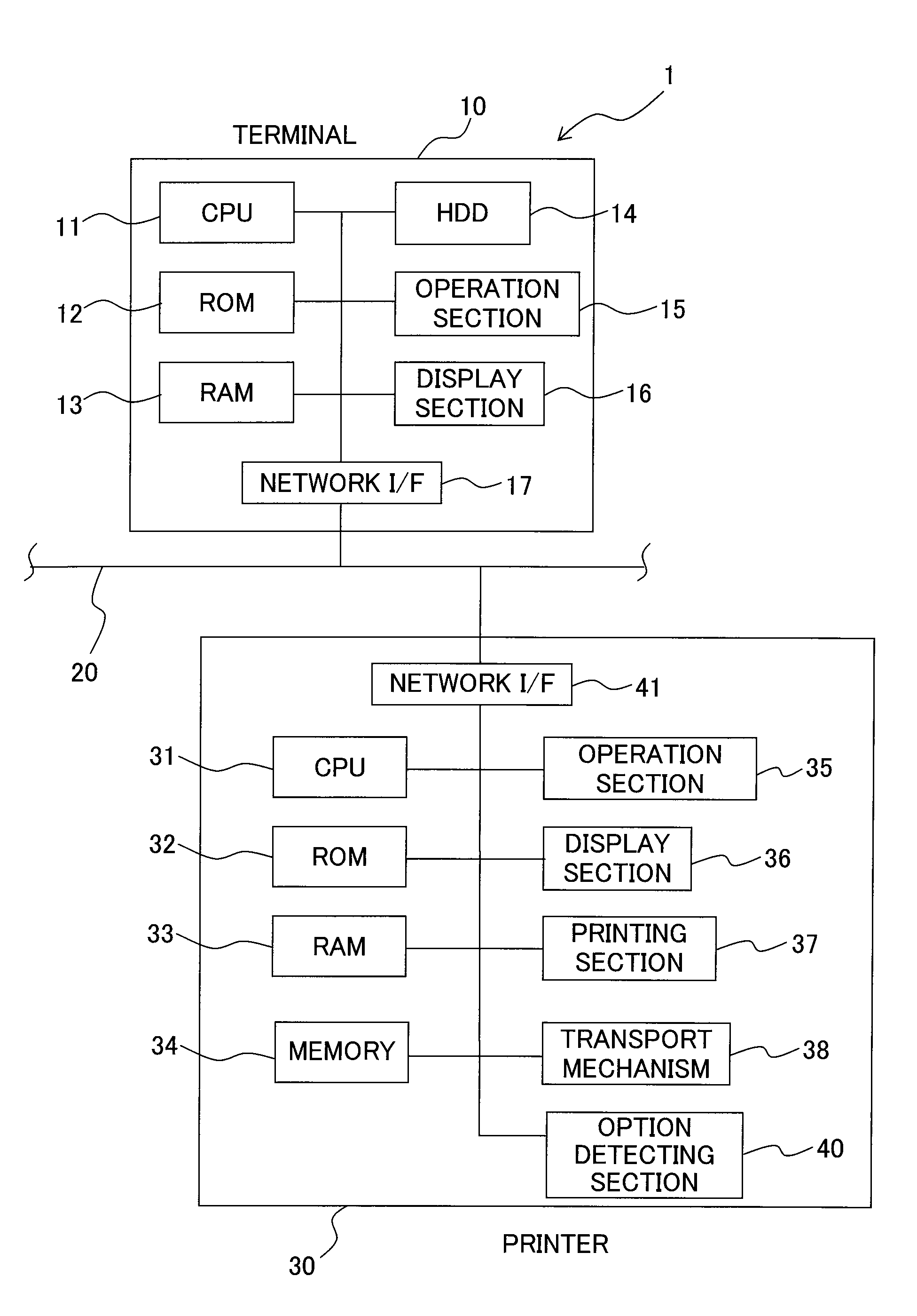
[0029]A printing system 1 is provided with a terminal 10 (for example a personal computer) and a printer 30 (an example of a printing apparatus). The terminal 10 is provided with a CPU 11, a ROM 12, a RAM 13, a hard disk drive (HDD) 14, an operation section 15 including a keyboard, a pointing device, etc., a display section 16 including a liquid crystal display etc., a network interface (network I / F) 17 connected to a communication line 20, and the like. Various programs, such as OS (operating system), application software which is capable of creating data for printing, a printer driver for controlling the printer 30, are stored in the hard disk drive 14.

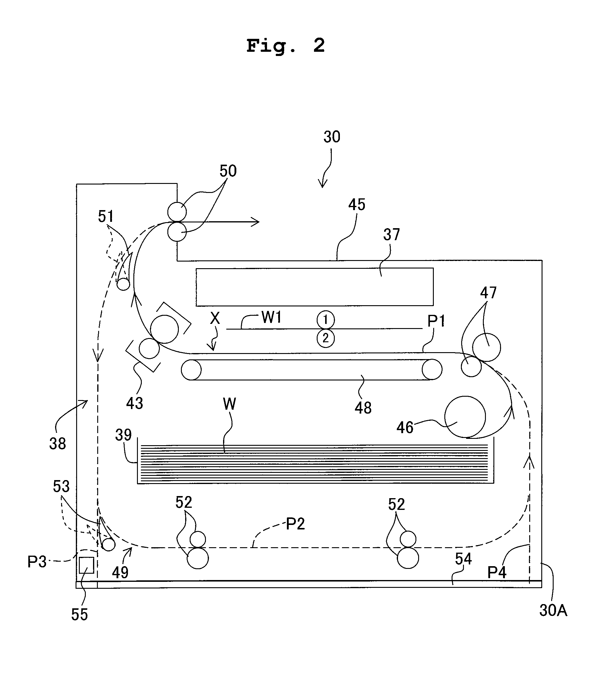
[0030]The printer 30 is provided with a main body 30A and an optional unit 60 (shown in FIG. 3 etc., an example of a transport unit) which is installable to the main body 30A. The main body 30A is provided wit...

second embodiment

[0079]Although the content of the printing process and a transportable width of the reversing transport path of the optional unit 60 are different between the first and second embodiments, all other respects are the same between the first and the second embodiments. Thus, constitutive parts or components, which are the same as or equivalent to those of the first embodiment, are designated by the same reference numerals, any explanation of which will be omitted as appropriate. Only those different from the first embodiment will be explained below.

[0080]As shown in FIG. 6, when the printing data, in which the double-sided printing is instructed, is received from, for example, the terminal 10, the CPU 31 executes the printing process. In this situation, the CPU 31 functions as the print control section.

[0081]At first, the CPU 31 judges whether the optional unit 60 is installed to the option install section 54 based on the detecting result from the option detecting section 55 (S11). Whe...


PUM


Abstract

There is provided a printing apparatus including: a printing section; a transport mechanism in which a transport route and a re-transport route are formed, the transport mechanism including an install section to which a transport unit is to be installed; and a print control section which controls the printing section and the transport mechanism to execute a plurality of kinds of double-sided printing processes having different maximum numbers of sheets present at the same time in the transport mechanism from each other so that in a case that the transport unit is installed to the install section, a double-sided printing process in which a maximum number of sheets is large as compared with a case in which the transport unit is not installed to the install section is executed.

Description

CROSS REFERENCE TO RELATED APPLICATION[0001]The present application claims priority from Japanese Patent Application No. 2011-018146, filed on Jan. 31, 2011, the disclosure of which is incorporated herein by reference in its entirety.BACKGROUND OF THE INVENTION[0002]1. Field of the Invention[0003]The present invention relates to a technique of a double-sided printing in which a sheet that has been printed on one surface is reversed and the printing on the other surface thereof is performed.[0004]2. Description of the Related Art[0005]As double-sided printing systems of printing apparatuses, there is well known a system in which printing on one surface of one paper sheet and the printing on the other surface of the one paper sheet are continuously performed and then the printing on one surface of a paper sheet which follows the one paper sheet and the printing on the other surface of the paper sheet which follows the one paper sheet are continuously performed (hereinafter referred to...

Claims


Application Information

Patent Timeline
Patent Type & Authority Patents(United States)
IPC IPC(8): B41J29/38
CPCB41J3/60
Inventor YAMADA, AKIHIRO
Owner BROTHER KOGYO KK
Features
  • R&D
  • Intellectual Property
  • Life Sciences
  • Materials
  • Tech Scout
  • Unparalleled Data Quality
  • Higher Quality Content
  • 60% Fewer Hallucinations
Learn More