

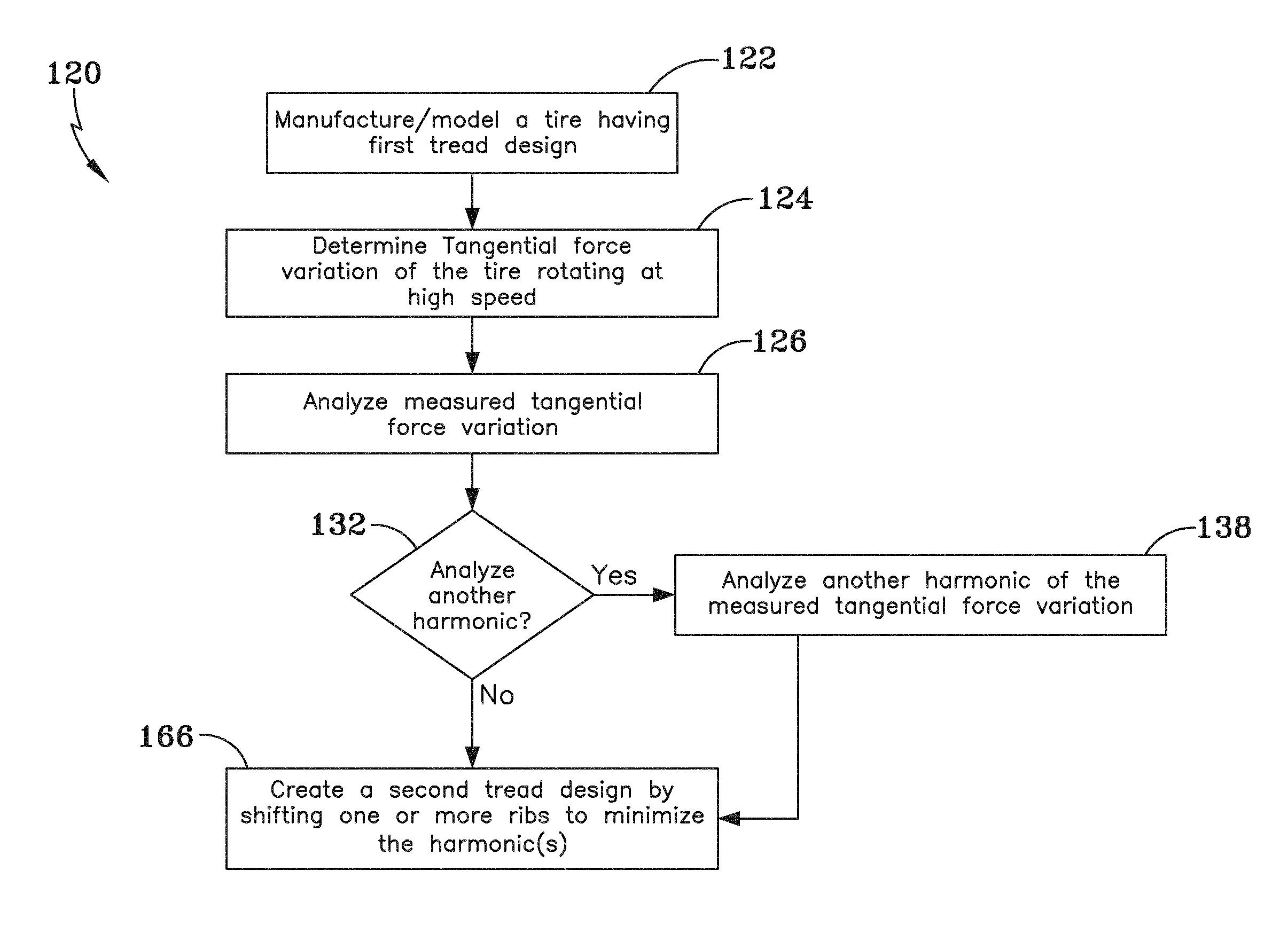
Tire second order harmonics with rib shift methodology
a second-order harmonic and rib shift technology, applied in the direction of instruments, non-skid devices, cad techniques, etc., to achieve the effect of minimizing the second-order harmonic of force variation
- Summary
- Abstract
- Description
- Claims
- Application Information
AI Technical Summary
Benefits of technology
Problems solved by technology
Method used
Image

Examples
Embodiment Construction
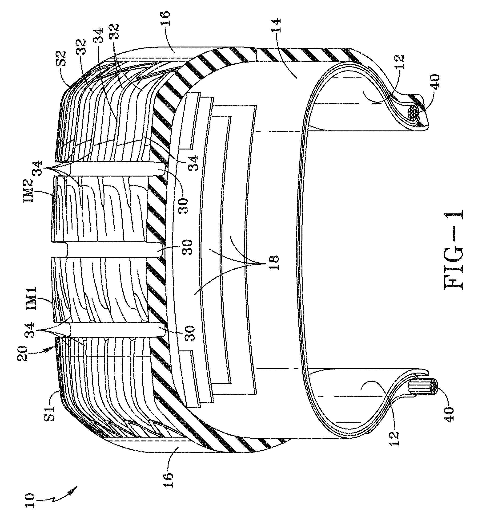
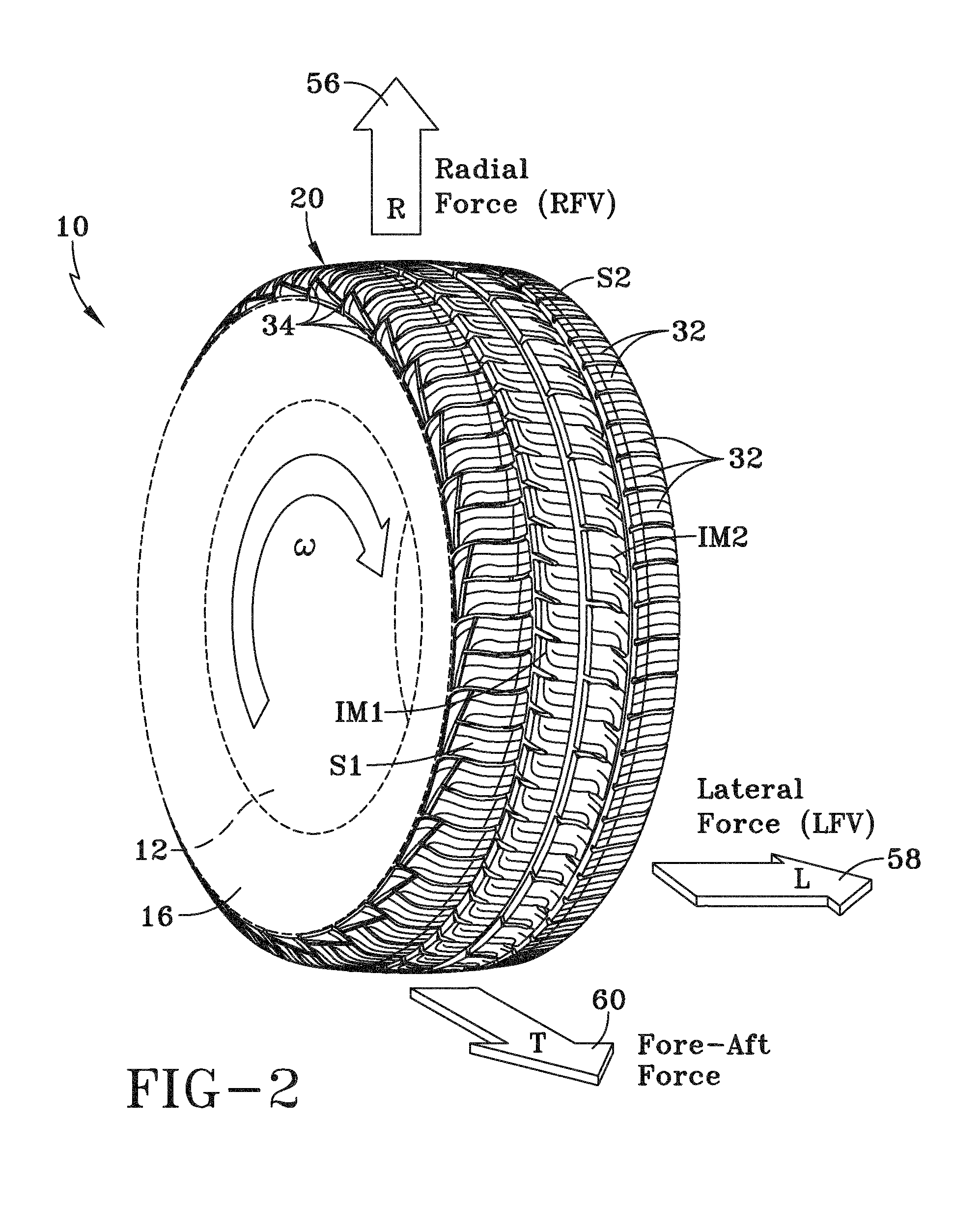
[0053]Referring now to the figures, and in particular to FIGS. 1-3, a pneumatic tire 10 (“tire”) is shown in partial cross-section. The tire 10 is a composite structure having an inner liner 12 for air containment within an air chamber (not shown), one or more plies 14 for providing a particular shape, sidewalls 16 for protecting the inner liner 12 and the one or more plies 14 from environmental elements, one or more belts 18 for increasing the tire stiffness, and a tire tread 20 (‘tread”). The tread 20 includes a particular design according to a desired function, such as wet and dry road traction, the likelihood of hydroplaning, noise level, vehicle handling during cornering, and steering response.
[0054]The tread 20, as shown in FIGS. 1 and 2, includes four ribs: a first shoulder rib S1, a second shoulder rib S2, and first and second intermediate ribs Im1, Im2. While not specifically shown, one or more medial ribs may also be included. The ribs S1, Im1, Im2, S2 form the circumferen...
PUM
 Abstract
Description
Claims
Application Information