Technique for protecting communication traffic in a connection having redundancy

a technology of communication traffic and redundancy, applied in the field of protected connectivity, can solve the problems of half as much traffic capacity and inacceptability, and achieve the effects of saving implementation efforts, fast recovery, and enhancing foam tools

Active Publication Date: 2014-05-13
ECE TELECOM LTD
View PDF15 Cites 7 Cited by
  • Summary
  • Abstract
  • Description
  • Claims
  • Application Information

AI Technical Summary

Benefits of technology

[0023] (A5) Recovery following a failure of a PE, or a PW, or a CE-PE connection should be automatic and fast, that is, completed in a short time (sub-second).
[0066]The method thereby allows said local node being remote from the failure, as well as all other local nodes in the network (if interconnected with said local node), to remain unaware of the failure, and thereby to continue forwarding the traffic normally.

Problems solved by technology

Solutions where normally only one of the CE-PE connections is active while the other is inactive (a.k.a, “standby”), thereby typically providing half as much traffic capacity, are not acceptable.

Method used


Image

  • Technique for protecting communication traffic in a connection having redundancy
  • Technique for protecting communication traffic in a connection having redundancy
  • Technique for protecting communication traffic in a connection having redundancy

Examples


Embodiment Construction

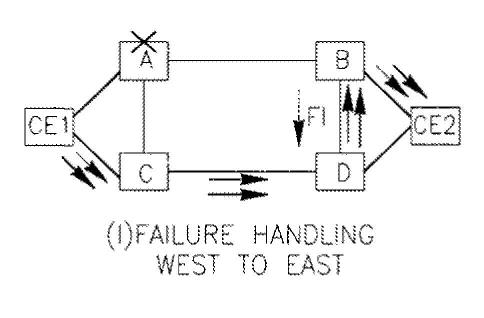
[0105]FIGS. 7A-7H illustrate scenarios of operation of a dual homed redundant structure under failure of one of its elements. Thin lines show pseudo-wires PW, fatter lines show CE to PE connections (local connections) created via VLAN or Ethernet.

[0106]FIGS. 7A-7H illustrate some of possible scenarios for the target topology, where CE1 (CE2) is dual homed to PE-A (abbrev. A) and C (B and D), respectively. A-B and C-D are P-PWs while the A-C and B-D are S-PWs. Traffic flow is described next.

(a) Normal Traffic Flow West to East:

[0107]Per rules R2 and R3:[0108] Packet sourced at CE1 (“West” side) is sent using load balancing to both A and C.[0109] A (C) forwards the packet over P-PW to B (D), respectively.[0110] B (D) forwards the packet directly to CE2 (“East” side), respectively.

(b) Normal Traffic Flow East to West:

[0111]Packet flow is similar to that described for case (a), but in the opposite directions. Note that per rule R10, B does not forward traffic to S-PW, as it associates a...


PUM


Abstract

A technique for protecting traffic in a Layer 2 (L2) communication network between a first and a second local nodes (CE1, CE2) interconnected via a redundant dual homed structure, the technique comprises a) distributing the traffic in the dual homed structure in a fault-free state, to form two traffic flows between the CE1 and CE2; b) providing Layer 2 (L2) fault indications for the dual homed structure, in the form of operation and maintenance (OAM) tools, c) in a faulty state of the dual homed structure, forwarding traffic packets at the provider edges of the structure, based only on conventional physical fault indications and L2 fault indications, by locally making forwarding decisions for selecting an active communication line via the redundant dual homed structure.

Description

CROSS-REFERENCE TO RELATED APPLICATIONS[0001]This application claims priority to Israel Application No. IL 210375 filed Dec. 30, 2010, the disclosure of which is incorporated by reference herein in its entiretyFIELD OF THE INVENTION[0002]The present invention relates to a technique for protected connectivity between layer 2 (L2) communication networks using connections with redundancy, and more particularly to a technique for redundant pseudowire connectivity for L2 virtual private networks (VPNs).BACKGROUND OF THE INVENTIONL2 Network[0003]A L2 network (abbreviated network) is composed of L2 bridges (a.k.a., L2 switches, switches) connecting local area networks (LAN) or IEEE 802.1Q virtual LAN (VLAN) segments containing end stations. A switch forwards L2 frames (packets) among its interfaces (ports) based on L2 media access control destination address (MAC DA) carried by each packet. A switch performs address learning based on L2 MAC source address (MAC SA) carried by each packet, a...

Claims


Application Information

Patent Timeline
Patent Type & Authority Patents(United States)
IPC IPC(8): H04L12/26H04L12/28
CPCH04L45/28H04L43/0811
Inventor NAKASH, SHELL
Owner ECE TELECOM LTD
Why Eureka
Try Eureka