Attachable assembly

a technology of attachable parts and smart phones, which is applied in the field of attachable parts for smart phones, can solve the problems of lack of mechanical strength, difficult design of extension devices for smart phones, and device limitations, and achieve the effect of convenient access, easy attaching and detaching from the smart phon

Inactive Publication Date: 2014-05-13
YANG SHENG LONG
View PDF2 Cites 11 Cited by
  • Summary
  • Abstract
  • Description
  • Claims
  • Application Information

AI Technical Summary

Benefits of technology

[0008]The primary object of the present invention is to have the smart phone conveniently access any type of extension device, and then easily attach and detach from the smart phone.
[0009]Another object of the present invention is to simplify the mechanical connection configuration between the smart phone and the extension device.
[0010]Yet another object of the present invention is to have sufficient mechanical strength to sustain the extension device from the smart phone.

Problems solved by technology

While the small size of such devices provides unprecedented convenience and accessibility for users, such devices suffer from certain limitations as a result of their very small size.
For example, the extension device for the smart phone is difficult to design and lacks for mechanical strength.
Therefore, no matter what resolution image can be achieved, the small size of the smart phone makes many fastening or fixing structures difficult, impractical or impossible to arrange.
This can be an even greater problem for users who always incautiously release and attach the extension device from the smart phone.
Therefore, while the evolution of smart phone technology presents a virtually unlimited growth in computer power, functional capability and wireless data speed, data input and display, such kind of mechanical problems may be occurred drastically.

Method used


Image

  • Attachable assembly
  • Attachable assembly
  • Attachable assembly

Examples


1st embodiment

1st Embodiment

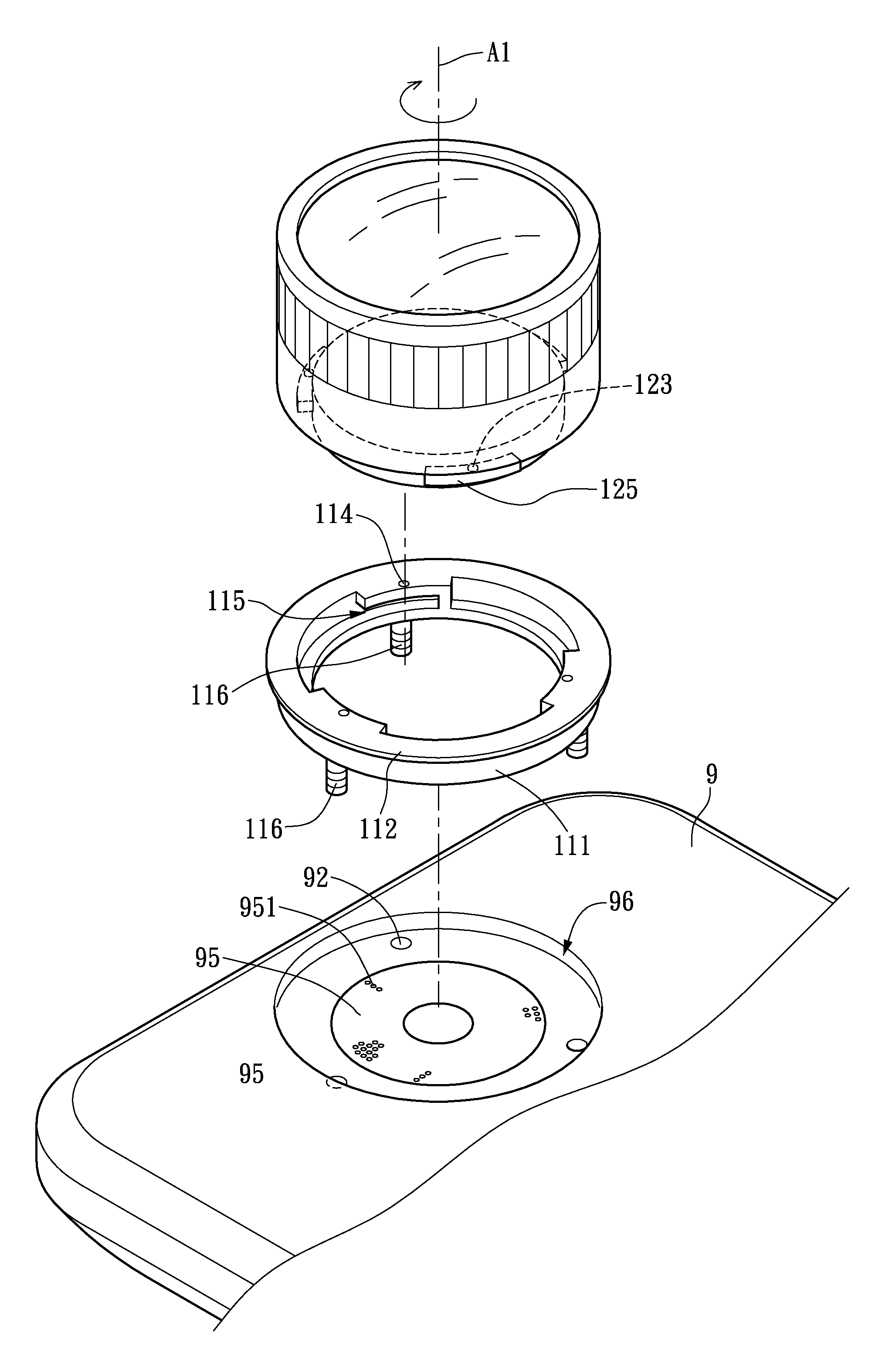
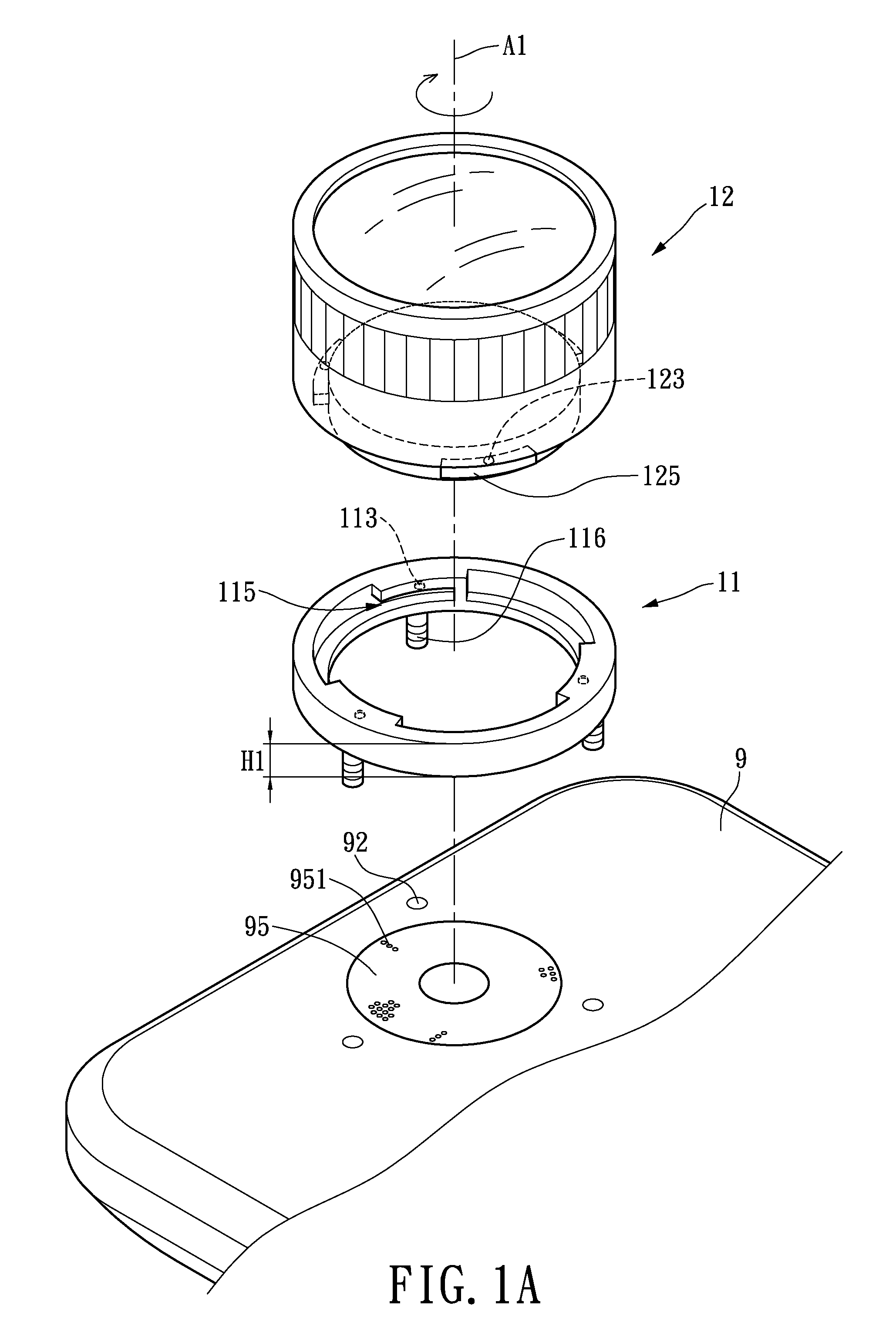
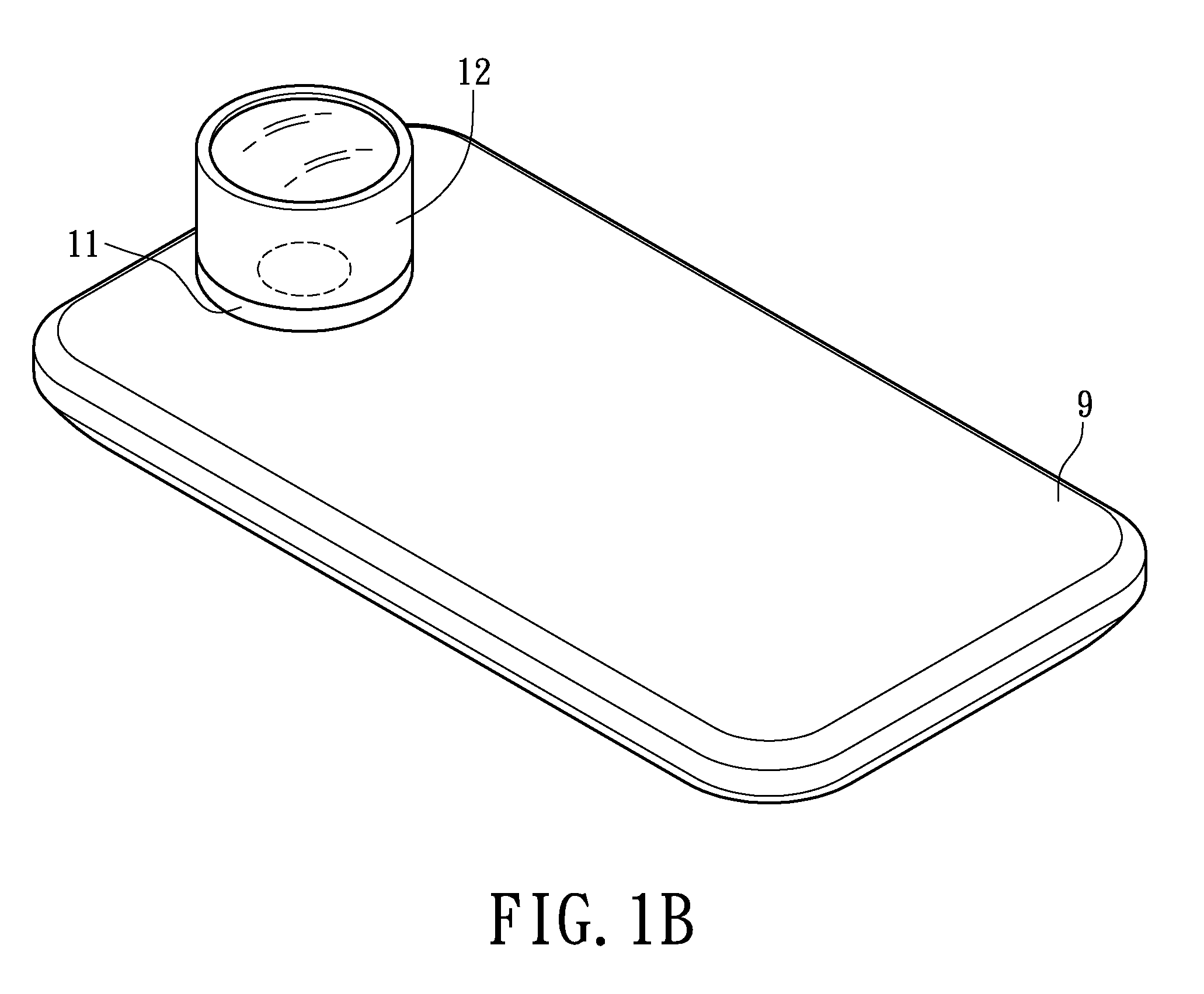
[0035]Referring to FIG. 1A to FIG. 1D, where the first embodiment of the instant disclosure provides an attachable assembly for a smart phone 9. The attachable assembly comprises a mount unit 11 fixing at upper edge of the smart phone 9, and an extension device 12 selectively connecting to the mount unit 11. Preferably, the mount unit 11 is arranged in the backboard, and therefore the extension device 12 is attached to the back side (as opposite to the screen in the front side) of the smart phone 9. The smart phone 9 further has a Printed Circuit Board (PCB) 95 disposed thereon. The extension device 12 is a camera module in this embodiment; however, it could be any electrical accessories for video or audio need, entertainment, wireless access, computing or controlling process, media storage, data transferring, internet connection, communication, or particularly image processing purpose. The smart phone 9 has at least one positioning hole 92 disposed on the outer surfac...

2nd embodiment

2nd Embodiment

[0039]Referring to FIG. 2, FIG. 2 shows a schematic view of the attachable assembly before installation according to the 2nd embodiment of the instant disclosure. In the following diagrams, similar component and structure is not addressed again. In this embodiment, the mount unit 11 is embedded in the smart phone 9; specifically, the smart phone 9 is hollowed out a cave 96 to receive the mount unit 11, so that whole or part of the mount unit 11 could be disposed below the upper surface of the smart phone 9. As a result, the PCB 95 and the contact sites 951 disposed at bottom of the cave 96 are absolutely required. Furthermore, the positioning holes 92 could be disposed at the circumference of the cave 96.

3rd embodiment

3rd Embodiment

[0040]Referring to FIG. 3A to FIG. 3C, the mount unit 11 has a body 111 to be received inside the cave 96, and a cap 112 to be retained at upper surface of the smart phone 9. As shown in FIG. 3B, several screws 93 pass through the cap 112 and fasten with screw hole 94 which can further increase the mechanical strength between the smart phone 9 and the mount unit 11; namely, the mount unit 11 can be firmly fixed on the smart phone 9 by the screws 93. As shown in FIG. 3A, the positioning holes 92 are disposed at bottom of the cave 96.

[0041]As shown in FIG. 3B and FIG. 3C, the mount unit 11 has a trough 114 disposed thereon and faced upward. The extension device 12 has a releasable tenon 124 faced downward to selectively fit to the trough 114. When the extension device 12 moves downward and rotates along the rotative axis A1, the locking member 125 may be rotated and then stopped rotation by means of matching the tenon 124 and the trough 114. Preferably, the tenon 124 is ...


PUM


Abstract

An attachable assembly for smart phone that has at least one contact site disposed thereon is disclosed. The attachable assembly comprises a mount unit and an extension device. The mount unit is fixed at one edge of the smart phone, and has at least one locking slot disposed thereon; the extension device electrically contacts the contact site and has at least one locking member selectively engaged to the locking slot. Wherein, the extension device has a rotative axis so that the extension device is rotated and fitted with the mount unit.

Description

BACKGROUND OF THE INVENTION[0001]1. Field of the Invention[0002]The present invention relates to an attachable assembly for smart phone, and more particularly to an attachable assembly for connecting any types of extension devices or accessories to the smart phone so as to provide the flexible capability.[0003]2. Description of Related Art[0004]In recent years mobile telephones have become much more than just telephones. Advanced mobile telephones, commonly referred to as “smart phones” have become powerful, ubiquitous computing devices, providing portable internet access, powerful computer processing ability and media storage. Such devices can access, store and play various media such as movies, photos, music, etc.[0005]Advances in smart phone technology have reached a point that, for many users such smart phones provide their primary access to the internet. It may even come to pass in the foreseeable future that such smart phones may be connected to any other host devices such as ...

Claims


Application Information

Patent Timeline
Patent Type & Authority Patents(United States)
IPC IPC(8): H04B1/38
CPCH04M1/0264G06F1/1656H04M1/0254H04N5/2257G06F1/1686H04M1/02H04N23/57
Inventor YANG, SHENG-LONG
Owner YANG SHENG LONG
Why Eureka
Try Eureka