
Lighted sign

a technology of leds and signs, applied in the field of leds, can solve the problems of limited existing systems, difficult if not near impossible field replacement of sign faces and/or leds, and difficult installation of such products, and achieve the effect of reducing power consumption and prolonging the life of leds

Active Publication Date: 2021-02-16
NEBULAE LLC
View PDF10 Cites 1 Cited by
  • Summary
  • Abstract
  • Description
  • Claims
  • Application Information

AI Technical Summary

Benefits of technology

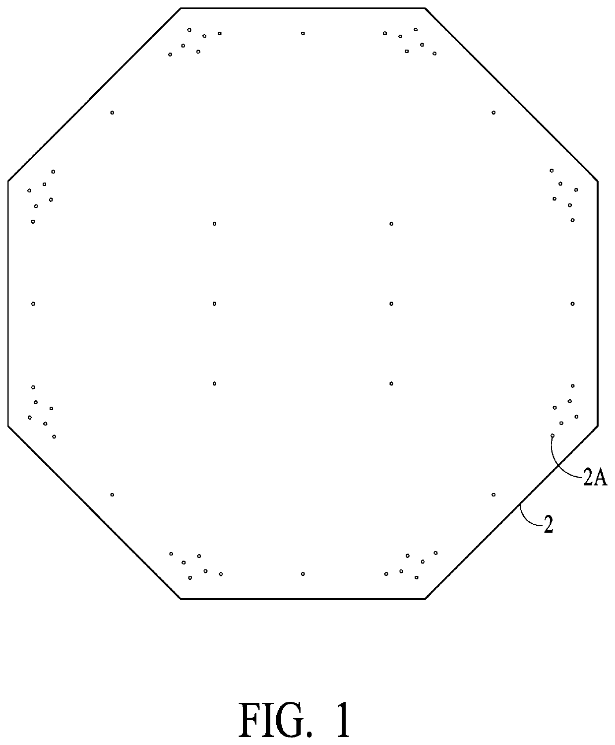
The present invention is about providing improved lighted signs and electronic signs with embedded or integral light sources. The LEDs provide a desirable and controllable level of output intensity, with each LED being driven at less than maximum brightness so as to achieve longer life of the LEDs, with lower power consumption. Furthermore, the LEDs can be controlled via PWM to manage both daytime and nighttime brightness. Controlling electronics are provided, including a central logic or flasher board and radio and other communication modules. A common portal can access and control a large number of devices, providing a convenient and efficient means of managing and monitoring multiple devices. The signals can be viewed on a map and on a graphical tree or similar representation for binding nodes and a gateway. The signs can also have a replaceable front indicia surface that can be readily removed and replaced. The back substrate can provide a rigid structure for securing solar panels or battery / control box, allowing for a solar-powered lighted sign assembly to be readily installed and mounted to a pole.

Problems solved by technology

There are limitations of existing systems, and there is a growing need for more advanced signage and lighting products.
Such products typically have the back ends of LEDs and / or wiring protruding through the back side of the sign face such that wiring for a plurality of LEDs may be routed to a power source / control electronics, which may be by way of a tube or conduit that go around the periphery of the back side of the sign, which may be unsightly or provide areas for water intrusion or vandalism, and which typically means that a solar panel mount or control box must located in some other location.
Typically, with such products, field replacement of sign faces and / or LEDs is difficult if not next to impossible.
Also, installation of such products is more difficult because separate provision must be made for installation of a box or container for housing electronics and one or more batteries, and for mounting a solar panel (in the case of a DC powered, solar system) or a power supply for an AC powered system.

Method used


Image

  • Lighted sign
  • Lighted sign
  • Lighted sign

Examples


Embodiment Construction

[0029]The present invention will be described in greater detail with reference to certain preferred and alternative embodiments. As described below, refinements and substitutions of the various embodiments are possible based on the principles and teachings herein.

[0030]In accordance with the present invention, lighted signs and in particular electronic signs having embedded or integral light sources are provided such as for flashing road warning signs and the like, and in particular lighted signs that have field replaceable lights (e.g., LEDs) and field replaceable face plates (e.g., stop sign face). In accordance with preferred embodiments, such LEDs / lights are preferably controlled by an Internet-connected controller. In accordance with certain preferred embodiments, the back substrate is sufficiently strong and rigid so as to provide an integral solar panel mount area and an integral battery box mount area such that the sign assembly may be readily installed on a pole in the oper...


PUM


Abstract

The present invention provides lighted signs and in particular electronic signs having embedded or integral light sources and in particular to lighted signs that have field replaceable lights and field replaceable face plates, and which preferably are controlled by an Internet-connected controller and which preferably includes an integral solar panel mount and an integral battery box mount, and still preferably include radios for pole-to-pole / machine-to-machine communication for synchronized control, and such products preferably having an additional network connection for Internet connectivity, such as by way of GPRS / GSM / cellular gateway functionality, WiFi, LAN, fiber optic or other network connectivity.

Description

[0001]This application claims priority on U.S. Provisional Application Ser. No. 62 / 731,071, filed Sep. 13, 2018, which is hereby incorporated by reference.FIELD OF THE INVENTION[0002]The present invention relates to lighted signs and in particular to electronic signs having embedded or integral light sources such as for flashing road warning signs and the like, and in particular to lighted signs that have field replaceable lights (e.g., LEDs) and field replaceable face plates (e.g., stop sign face), and which preferably is controlled by an Internet-connected controller and which preferably includes an integral solar panel mount and an integral battery box mount such that the sign assembly may be readily installed on a pole in the operative environment, and still preferably such products include radios for pole-to-pole / machine-to-machine communication for synchronized control, and such products preferably having an additional network connection for Internet connectivity, such as by w...

Claims


Application Information

Patent Timeline
Patent Type & Authority Patents(United States)
IPC IPC(8): G09F13/04F21V19/04F21V19/00F21S9/03F21S10/06F21W111/02H02J7/35F21Y115/10
CPCF21V19/04F21S9/037F21V19/001G09F13/04F21S10/06F21W2111/02F21Y2115/10G09F2013/049G09F2013/0472H02J7/35G09F27/004G09F27/007G09F27/00G09F13/0472H02J7/0042G09F13/049
Inventor PATEL, PARESHLOUDERMILK, ALAN
Owner NEBULAE LLC
Learn More