Handle-dampening lacrosse stick

a technology of lacrosse stick and handle, which is applied in the field of lacrosse sticks, can solve the problems of difficult to catch and control thrown balls, and the failure of the monolithic double wall head to outperform

Inactive Publication Date: 2014-05-20
WM T BURNETT IP
View PDF9 Cites 19 Cited by
  • Summary
  • Abstract
  • Description
  • Claims
  • Application Information

AI Technical Summary

Benefits of technology

[0009]It is, therefore, an object of the present invention to provide a method and apparatus for dampening the rebound of a lacrosse head pocket after the pocket has had force applied to it by, for example, a thrown lacrosse ball.
[0010]Unlike the substantially rigid lacrosse head frames of the prior art, which attach pocket thread to unforgiving, rigid structures, the present invention provides a flexible energy-absorbing material within or as part of the handle where the rigid head and handle meet. The material within or attached to the handle is part of an otherwise rigid handle. The flexibility of the material produces a “give” that minimizes the rebound of a pocket after being impacted by a ball. This pocket dampening limits the movement of the ball and makes the ball easier to control and to retain in the pocket. The precise location of the dampening material on the lacrosse handle may be varied to control the degree of pocket “give” in response to, for example, the force on the pocket created by a ball impacting the pocket during a catch or swinging in the pocket during cradling.

Problems solved by technology

Although the synthetic materials used in the construction of the head impart many performance advantages over traditional wooden heads, the synthetic, monolithic double-wall head fails to outperform the wooden heads in one critical aspect: pocket “give.” Specifically, whereas traditional unitary single walled wooden and gut sticks deflected under the force of a caught ball, the strength and rigidity of synthetics required for head durability combined with the rigid metal shaft is at odds with the desire for the pocket to “give” in order to facilitate catching the heavy, hard rubber lacrosse ball.
This makes it difficult to catch and control thrown balls, particularly balls thrown at high velocity.

Method used


Image

  • Handle-dampening lacrosse stick
  • Handle-dampening lacrosse stick
  • Handle-dampening lacrosse stick

Examples


Embodiment Construction

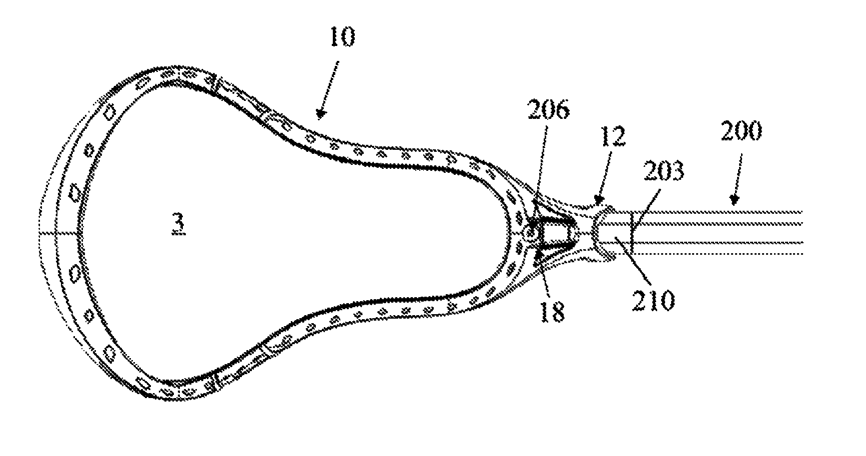
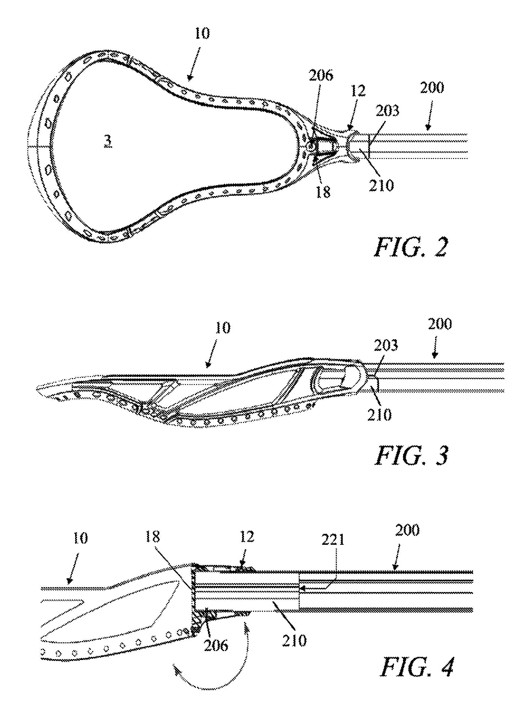
[0026]The present invention is an apparatus and method for dampening the rebound of a lacrosse head after the head has had force applied to it by, for example, a lacrosse ball being caught in its pocket. FIG. 2 is a bottom perspective view and FIG. 3 is a side view of an exemplary embodiment of the present invention, which generally includes a lacrosse head 10 defining a pocket 3 and a hollow lacrosse handle or shaft 200 extending from the head as described above. The shaft is received in a throat as will be described and is typically of a hollow, rounded hexagonal, octagonal, oval or circular cross section and made of metal or composite materials. The top end of the shaft (where the shaft meets the head) is shaped and contoured to receive a resilient insert 210 therein to achieve the purposes of the invention as will also be described. It should be noted that the relatives terms such as “top,”“bottom,”“front” and “back” are used herein to describe the invention as depicted in the a...


PUM


Abstract

A lacrosse stick for reducing the rebound of a ball caught therein. The head of the lacrosse stick is affixed to a tubular shaft in which a portion of the shaft wall at the top end is omitted on the front side and another portion is omitted on the backside below the first omitted portion. A resilient member is inserted within the shaft extending past the lower omitted portion of the shaft wall. The resilient member fills the omitted areas to seat flush therein. A head having a socket and throat is affixed to top end of the shaft. The socket engages the resilient insert via the omitted portions. When a force is applied, for example, by a ball caught in the pocket, the socket compresses the resilient member from the front and the throat from the back allowing the head to rotate backward, dissipating some of the energy and reducing rebound.

Description

CROSS-REFERENCE TO RELATED APPLICATIONS[0001]The present application claims priority to U.S. provisional patent application Ser. No. 61 / 390,339 filed Oct. 6, 2010 which is incorporated herein by reference.BACKGROUND OF THE INVENTION[0002]1. Field of the Invention[0003]The present invention relates generally to lacrosse sticks, and more particularly to an apparatus and method for dampening the rebound of a lacrosse stick head pocket after the pocket has had force applied to it by, for example, a caught lacrosse ball.[0004]2. Description of the Background[0005]FIG. 1 illustrates a conventional molded-head lacrosse stick. As shown, a typical lacrosse stick includes a handle or shaft 20 (dashed lines) and a double-wall synthetic head 10. Head 10 includes a generally V-shaped frame having two sidewalls 14A, 14B joined by a stop member 18 at the end narrow end of the “V,” nearest the shaft 20. A transverse wall (or “scoop”) 16 joins the sidewalls 14A, 14B at the open end of the “V.” Webbi...

Claims


Application Information

Patent Timeline
Patent Type & Authority Patents(United States)
IPC IPC(8): A63B65/12A63B59/02
CPCA63B59/0059A63B59/0014A63B59/0092A63B59/0088A63B59/02A63B59/20A63B60/06A63B60/08A63B60/10A63B60/26A63B60/50A63B60/54
Inventor LIGNELLI, JOANNAABDELMALEK, ANTHONY
Owner WM T BURNETT IP
Why Eureka
Try Eureka