Procesing equipment capable of improving plate part formation limitation and method therefor

A technology of forming limit and processing device, used in forming tools, metal processing equipment, manufacturing tools, etc., can solve the problems of processing cost, long processing cycle, accumulation of multiple forming errors, and inability to realize part forming, so as to avoid cracking defects. , The effect of improving the uniformity of the wall thickness of the parts and not easy to scratch

Inactive Publication Date: 2007-01-31
HARBIN INST OF TECH
View PDF0 Cites 32 Cited by
  • Summary
  • Abstract
  • Description
  • Claims
  • Application Information

AI Technical Summary

Problems solved by technology

Complex parts with larger height-to-diameter ratios and higher forming limits cannot be formed in one process only by back pressure. Multi-pass forming not only causes processing costs and long processing cycles, but also accumulates errors in multi-pass forming. Affects the accuracy of parts, and cannot meet the requirements of special use conditions in the aviation and aerospace fields for part wall thickness and aerodynamic performance.

Method used


Image

  • Procesing equipment capable of improving plate part formation limitation and method therefor
  • Procesing equipment capable of improving plate part formation limitation and method therefor

Examples


specific Embodiment approach 1

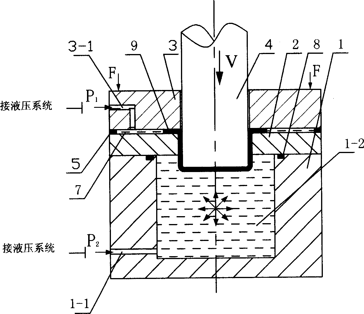
[0022] Specific implementation mode 1: This implementation mode is a processing device that can improve the forming limit of plate parts, refer to figure 1 , which includes a fluid medium cavity 1, the cavity 1 is provided with a liquid injection hole 1-1 communicating with the cavity 1-2, and the fluid medium is injected into the cavity 1 through the liquid injection hole 1-1 during operation; The upper end of the cavity 1 is open, and a lower die 2 is fixed above the cavity 1, and a sealing ring 8 is provided between the cavity 1 and the lower die 2 to prevent leakage of the fluid medium; The upper blankholder 3 and the punch 4, the blank 9 is sandwiched between the blankholder 3 and the lower die 2, the blankholder 3 is provided with a liquid injection hole 3-1, and the lower die 2 and the blankholder There is a gap 7 suitable for the thickness of the plate to be formed between the rings 3, and the liquid injection hole 3-1 communicates with the gap 7, so that the injected ...

specific Embodiment approach 2

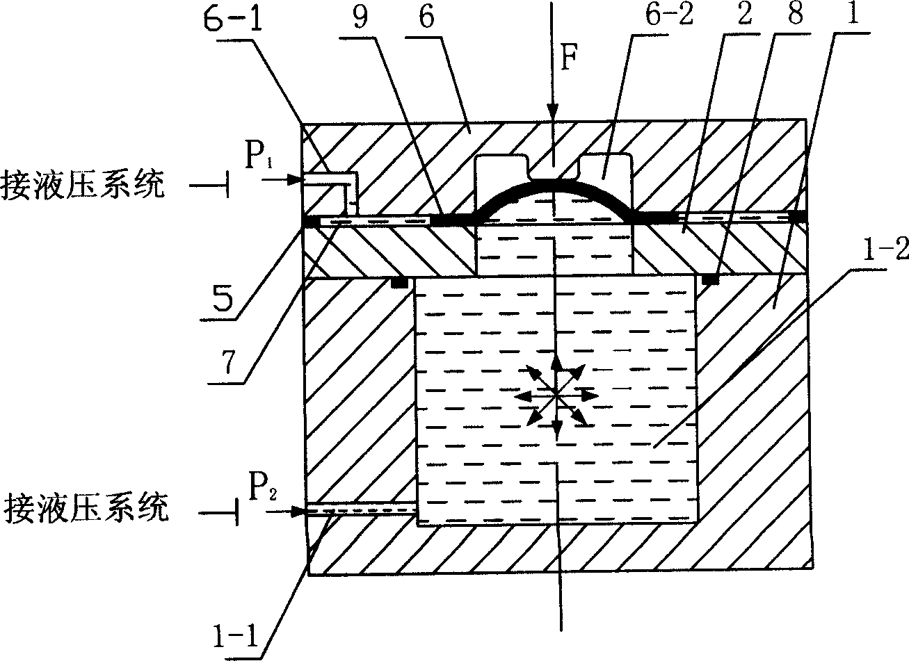
[0031] Specific implementation mode two: refer to figure 2 , this embodiment includes a fluid medium chamber 1, the chamber 1 is provided with a liquid injection hole 1-1 communicating with the chamber body 1-2, through which the liquid injection hole 1-1 is connected to the hydraulic system, the chamber can be 1 is injected with a fluid medium; the upper end of the cavity 1 is open, and a lower die 2 is fixed above the cavity 1, an inner hole is provided on the lower die 2, and a sealing ring is provided between the cavity 1 and the lower die 2 8, to prevent fluid medium leakage; it also includes a forming die 6 arranged above the lower die 2, a groove 6-2 is provided at a position where the lower bottom surface of the forming die 6 is adapted to the inner hole of the lower die 2, When working, the blank 9 is placed between the forming die 6 and the lower die 2, and the blank 9 is gradually deformed under the action of the fluid medium in the cavity 1 and abuts against the g...


PUM

PropertyMeasurementUnit
strengthaaaaaaaaaa
strengthaaaaaaaaaa
plasticityaaaaaaaaaa

Abstract

An apparatus for increasing the forming limit of plate part is composed of a fluid medium cavity, a lower female die, an edge pressing ring, and a male die or a forming female die. Its forming method includes such steps as filling fluid medium in said cavity, putting a raw plate on the working position, applying an edge-pressing force, and controlling the male die to move downward.

Description

technical field [0001] The invention relates to a device used for processing boards and a method for processing boards using the device. Background technique [0002] In sheet metal forming, for sheet parts with high forming limit (large amount of deformation) whose shape and size are consistent with the punch, fluid is usually used as the force transmission medium for forming processing. The principle is to make the sheet under the action of fluid back pressure Close to the punch, the back pressure enhances the friction effect between the blank and the punch, forming a beneficial friction force, which can offset part of the tensile stress of the blank at the rounded corner of the punch, improve the bearing capacity of the deformed blank, and thus increase the forming limit of the sheet metal part. The forming technology of plate parts with fluid as the force transmission medium has been paid more and more attention due to its advantages of high process flexibility, simple m...

Claims


Application Information

Patent Timeline
Patent Type & Authority Applications(China)
IPC IPC(8): B21D26/02B21D37/10B21D37/12B21D35/00B21D26/021
Inventor 苑世剑徐永超陈宇康达昌
Owner HARBIN INST OF TECH
Why Eureka
Try Eureka