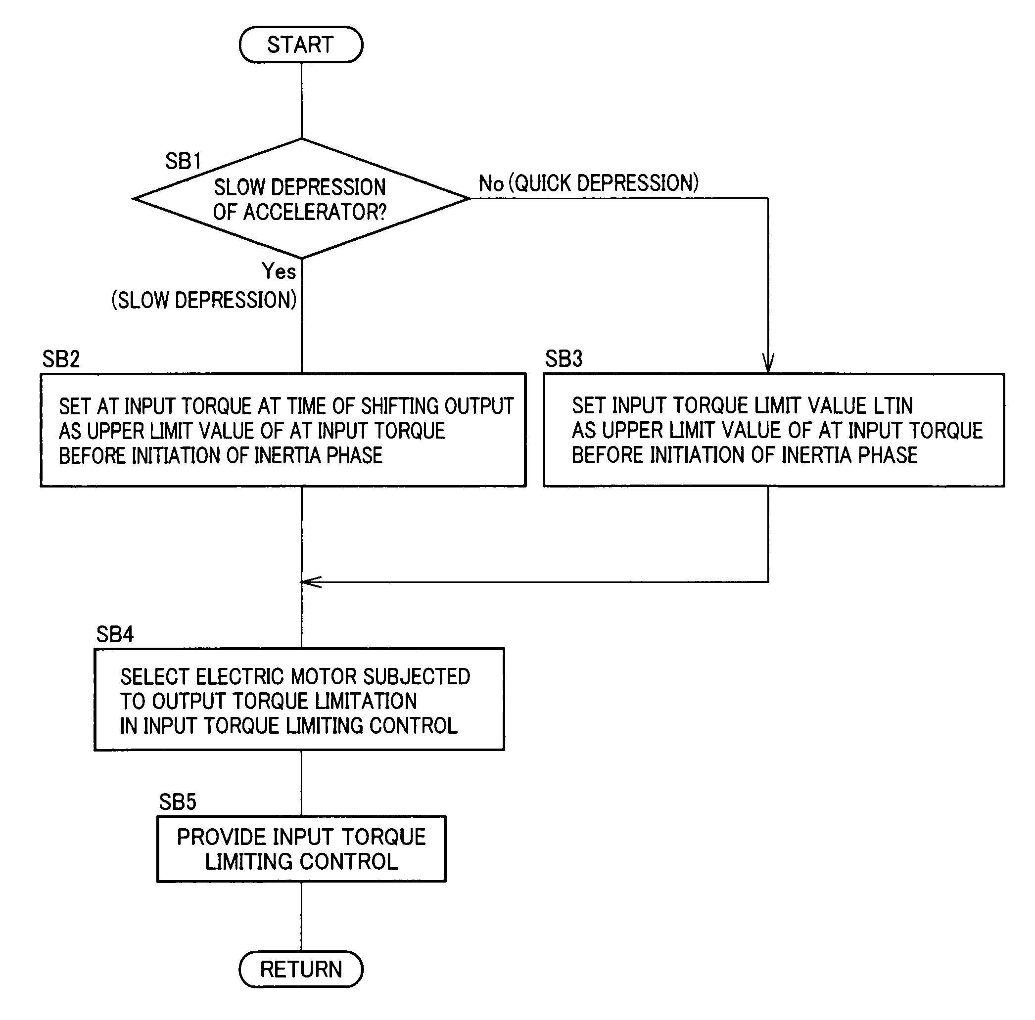
[0016]According to the control device for a vehicle drive device of the first aspect of the invention, if a downshift of the automatic shifting portion is executed during the accelerator depressing operation, the input torque limiting control means provides the input torque limiting control to limit the input torque before the initiation of the inertia phase in the downshift of the automatic shifting portion as compared to the case of not executing the downshift and, therefore, the two-stage acceleration shock can be alleviated during the power-on downshift. Since the engine torque has a certain amount of response delay to a throttle position change, if the accelerator variation is smaller, the engine torque is increased in a manner sufficiently following the accelerator variation while if the accelerator variation is larger, the engine torque is increased with a delay relative to the accelerator variation. Therefore, although it is contemplated that the input torque is increased to the extent that the initial response can be ensured to a level not causing deterioration at the time of the shifting output if the accelerator variation is smaller, it is contemplated that the input torque is not increased to the extent that the initial response can be ensured at the time of the shifting output if the accelerator variation is larger. In this regard, according to the control device of the first aspect of the invention, in the input torque limiting control, if the accelerator variation determining means determines that the accelerator variation is equal to or less than the accelerator variation limit, the input torque limiting control means limits the input torque before the initiation of the inertia phase in the downshift to the input torque at the time of the shifting output commanding the execution of the downshift while if the accelerator variation before the initiation of the downshift is greater than the accelerator variation limit, the input torque is limited before the initiation of the inertia phase equal to or less than a predetermined input torque limit value greater than the input torque at the time of the shifting output. Therefore, in consideration of the response delay of the input torque relative to the accelerator variation, if the accelerator variation is larger and the rising of the input torque is delayed, the input torque is limited when the input torque is increased to some extent and, therefore, the deterioration of the initial response can be suppressed while the two-stage acceleration shock is alleviated during the power-on downshift. Therefore, the improvement of the drivability may be achieved.
[0017]According to the control device for a vehicle drive device of the second aspect of the invention, the accelerator variation may correspond to the accelerator operation speed and the accelerator variation limit may be the accelerator operation speed determination value determined in advance for the accelerator operation speed. As a result, the upper limit value of the input torque to the automatic shifting portion in the input torque limiting control can be determined based on the accelerator operation speed.
[0018]According to the control device for a vehicle drive device of the third aspect of the invention, the accelerator variation may correspond to the accelerator operation amount and the accelerator variation limit may be the accelerator operation amount determination value determined in advance for the accelerator operation amount. As a result, the upper limit value of the input torque to the automatic shifting portion in the input torque limiting control can be determined based on the accelerator operation amount
[0019]According to the control device for a vehicle drive device of the fourth aspect of the invention, (a) the power source is made up of the engine capable of transmitting power to an input rotating member of the automatic shifting portion and one or two or more electric motors, and (b) if a downshift of the automatic shifting portion is executed during an accelerator depressing operation, the input torque limiting control is provided by output torque limitation of the one or two or more electric motors. Therefore, it is not or almost not necessary to reduce the engine torque in order to limit the input torque to the automatic shifting portion, and after the end of the input torque limiting control, the input torque can be increased in a responsive manner depending on the accelerator variation to ensure sufficient initial response.
[0020]According to the control device for a vehicle drive device of the fifth aspect of the invention, (a) the power source includes a first electric motor and a second electric motor included in the one or two or more electric motors, wherein (b) the control device is disposed with a electric storage device capable of giving / receiving electric power to / from each of the first electric motor and the second electric motor, wherein (c) during charging power limitation while a charging power to the electric storage device is limited lower than a predetermined allowable charging power, the input torque limiting control is provided by the output torque limitation of the first electric motor or the second electric motor that has an electric power balance of the electric storage device toward the discharging side, and wherein if not during the charging power limitation, the input torque limiting control is provided by the output torque limitation of the first electric motor or the second electric motor that is associated with the electric power balance of the electric storage device toward the charging side. Therefore, even during the charging power limitation, the input torque limiting control may be provided to achieve the improvement of the drivability. If not during the charging power limitation, the charging of the electric storage device is promoted and the improvement of the fuel economy may consequently be achieved.
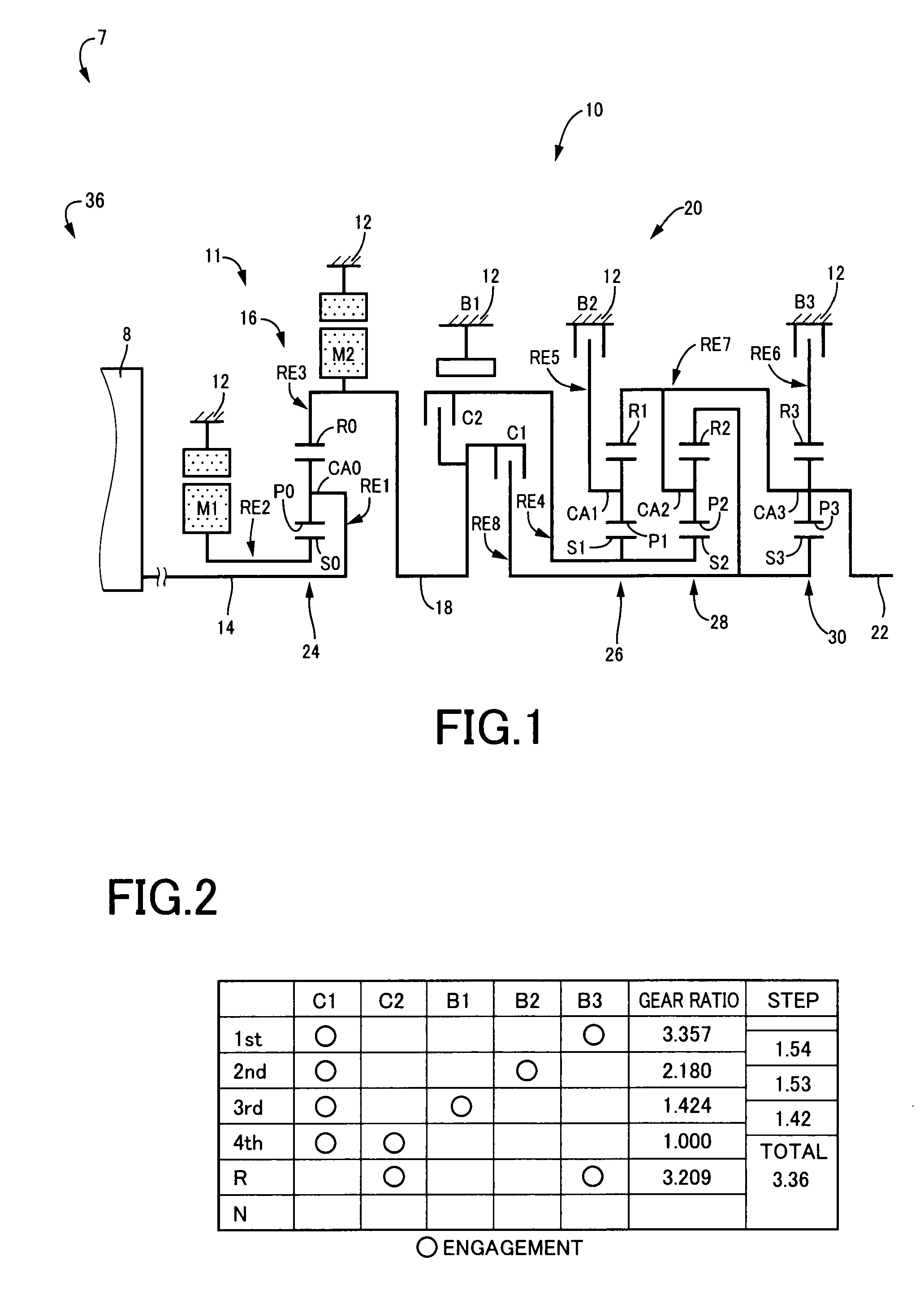
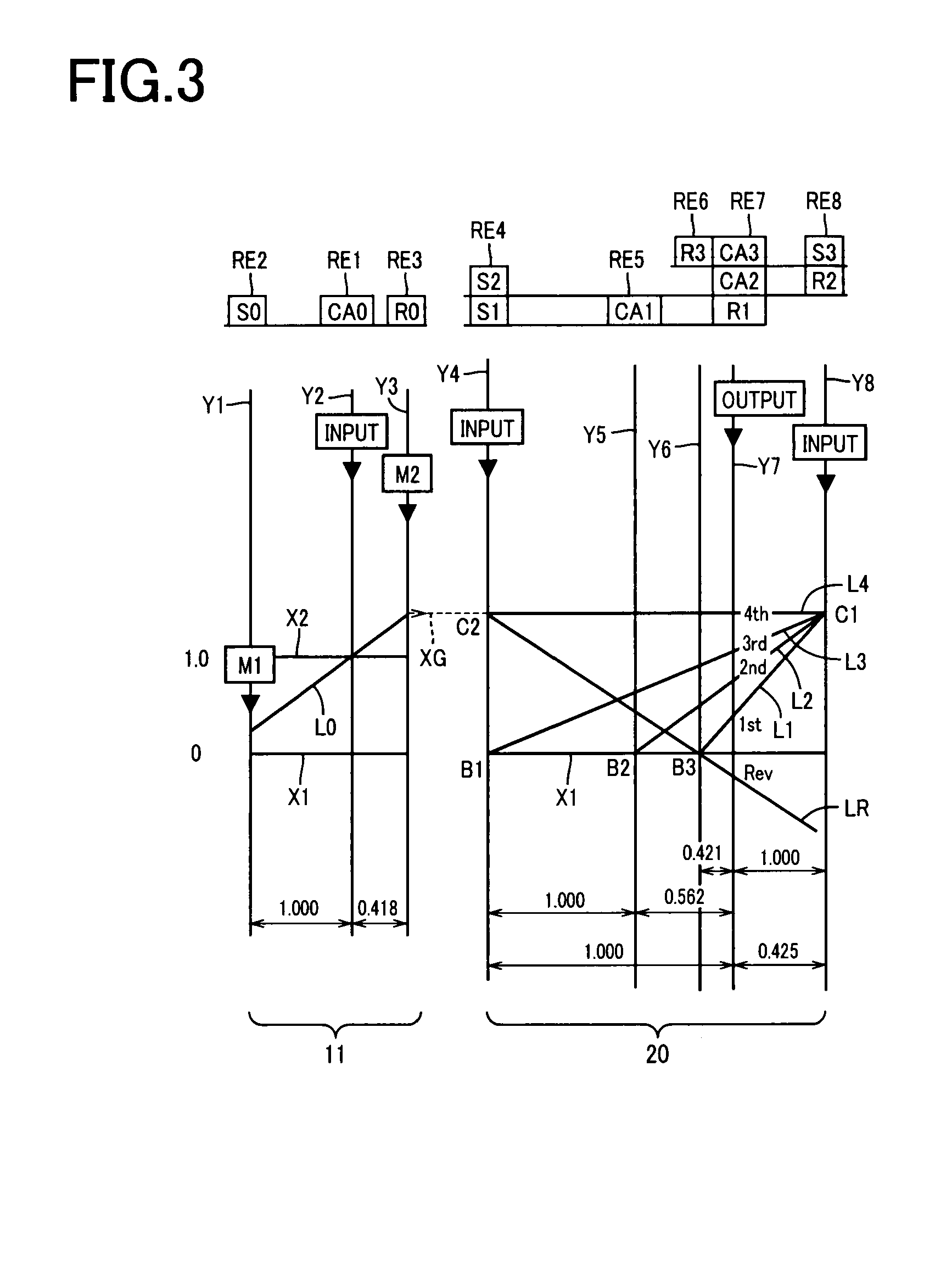
[0021]According to the control device for a vehicle drive device of the sixth aspect of the invention, (a) the power source includes a differential mechanism having different rotating elements respectively coupled in a power transmittable manner to the engine, the first electric motor, and the input rotating member, wherein (b) the second electric motor is coupled in a power transmittable manner to the input rotating member, and wherein (c) the differential state of the differential mechanism is controlled by controlling an operation state of the first electric motor. Therefore, since the gear ratio of the differential mechanism can continuously be changed by the first electric motor through the power transmission from the engine to the input rotating member, the engine can be driven such that the engine rotation speed is not restricted by the rotation speed of the input rotating member so as to improve the fuel economy of the vehicle.
[0022]According to the control device for a vehicle drive device of the seventh aspect of the invention, during discharging power limitation while a discharging power of the electric storage device is limited lower than a predetermined allowable discharging power as well as the charging power limitation, the input torque limiting control is provided by the output torque limitation of the first electric motor and the second electric motor on the condition that one of the first electric motor and the second electric motor generates electric power while the other consumes electric power. Therefore, even during both the discharging power limitation and the charging power limitation, the improvement of the drivability may be achieved by providing the input torque limiting control while the electric power balance of the electric storage device is brought closer to zero.
[0023]According to the control device for a vehicle drive device of the eighth aspect of the invention, in the input torque limiting control, the input torque to the automatic shifting portion before the initiation of the inertia phase is limited as compared to the case of not executing the shift of the automatic shifting portion. Therefore, the criteria of limiting the input torque can be clarified.
[0024]According to the control device for a vehicle drive device of the ninth aspect of the invention, if the output torque of the automatic shifting portion at the time of the shifting output is equal to or greater than a predetermined output torque determination value, the control device determines that the accelerator variation before the start of the downshift is equal to or less than the accelerator variation limit, and wherein if the output torque of the automatic shifting portion at the time of the shifting output is less than the output torque determination value, the control device determines that the accelerator variation before the start of the downshift is greater than the accelerator variation limit. As a result, the upper limit value of the input torque in the input torque limiting control can be determined based on the output torque of the automatic shifting portion by calculating or detecting the output torque of the automatic shifting portion.
[0025]Preferably, in the power transmission path between the engine and the drive wheels, the engine, the differential mechanism, the automatic transmission, and the drive wheels are coupled together in the mentioned order.

