
Vehicle and control method

a technology of vehicle and control method, applied in the field of vehicles, can solve the problems of reducing the response of the driving force and deteriorating the driveability, and achieve the effect of less likely to suffer from deterioration of the driveability

Active Publication Date: 2014-09-09
TOYOTA JIDOSHA KK
View PDF7 Cites 4 Cited by
  • Summary
  • Abstract
  • Description
  • Claims
  • Application Information

AI Technical Summary

Benefits of technology

[0007]The invention was developed in view of the above situation, and provides a vehicle having an engine and a motor, and a control method therefor, which is less likely to suffer from deterioration of the driveability when the engine is started while the vehicle is running with power of the motor.
[0009]With the above arrangement, even if the motor speed is high when the engine is started in the motor running mode, the intake air amount of the engine is increased due to advancement of the intake valve timing, in accordance with the motor speed. As a result, engine torque is increased. Thus, the period of time it takes from the time when engine starting is initiated to the time when the engine speed becomes equal to the motor speed, namely, the period of time it takes from the time when engine starting is initiated to the time when the clutch is fully engaged, is less likely or unlikely to be prolonged due to the high motor speed. Accordingly, when the engine is started in the motor running mode, deterioration of the driveability, such as reduction of the response of the driving force, can be curbed. The intake valve timing means at least the valve-closing timing of the intake valve, and may mean the valve-opening timing and valve-closing timing of the intake valve.
[0010]The vehicle as described above may be configured as follows. The control unit is configured to increase a throttle opening of the engine after the engine starting control is initiated, when the engine is started in the motor running mode, and the control unit is configured to increase the throttle opening at an earlier point in time as the rotational speed of the motor detected when the engine is started in the motor running mode is higher. With this arrangement, the intake air amount of the engine increases due to the increase of the throttle opening, in accordance with the motor speed. Accordingly, even if the motor speed is high when the engine is started in the motor running mode, engine torque is increased in accordance with the motor speed. Consequently, the period of time it takes from the time when engine starting is initiated to the time when the clutch is fully engaged is less likely or unlikely to be prolonged due to the high motor speed. Accordingly, when the engine is started in the motor running mode, deterioration of the driveability, such as reduction of the response of the driving force, can be curbed.
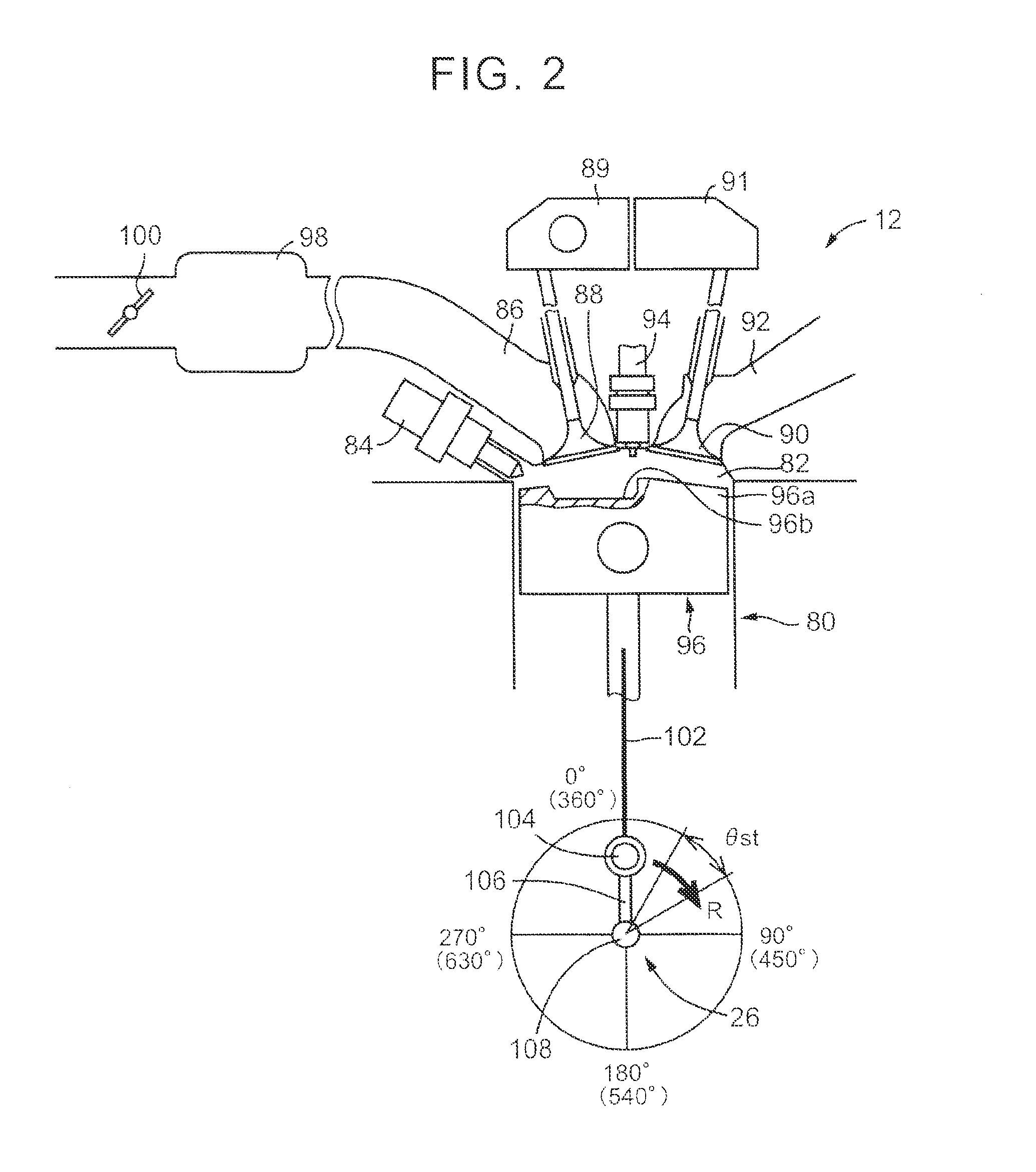
[0011]The vehicle as described above may be configured as follows. The control unit is configured to advance the intake valve timing, after the intake valve is closed in an cylinder in which the intake valve is open at a time when starting of the engine is initiated, and a piston approaches a top dead center first since the time when starting of the engine is initiated. When the engine is started, compression torque that appears in the cylinder that approaches the top dead center first when the engine starts being rotated results in rotational resistance of the engine. However, if the intake valve timing is advanced in the above-described manner, the compression torque is less likely or unlikely to affect rotation of the engine. Accordingly, it is possible to quickly complete engine starting without unnecessarily increasing the rotational resistance of the engine.

Problems solved by technology

As a result, the driveability may deteriorate; more specifically, the driver may feel uncomfortable, or the response of the driving force may be reduced.

Method used


Image

  • Vehicle and control method
  • Vehicle and control method
  • Vehicle and control method

Examples


Embodiment Construction

[0021]One embodiment of the invention will be described in detail with reference to the drawings.

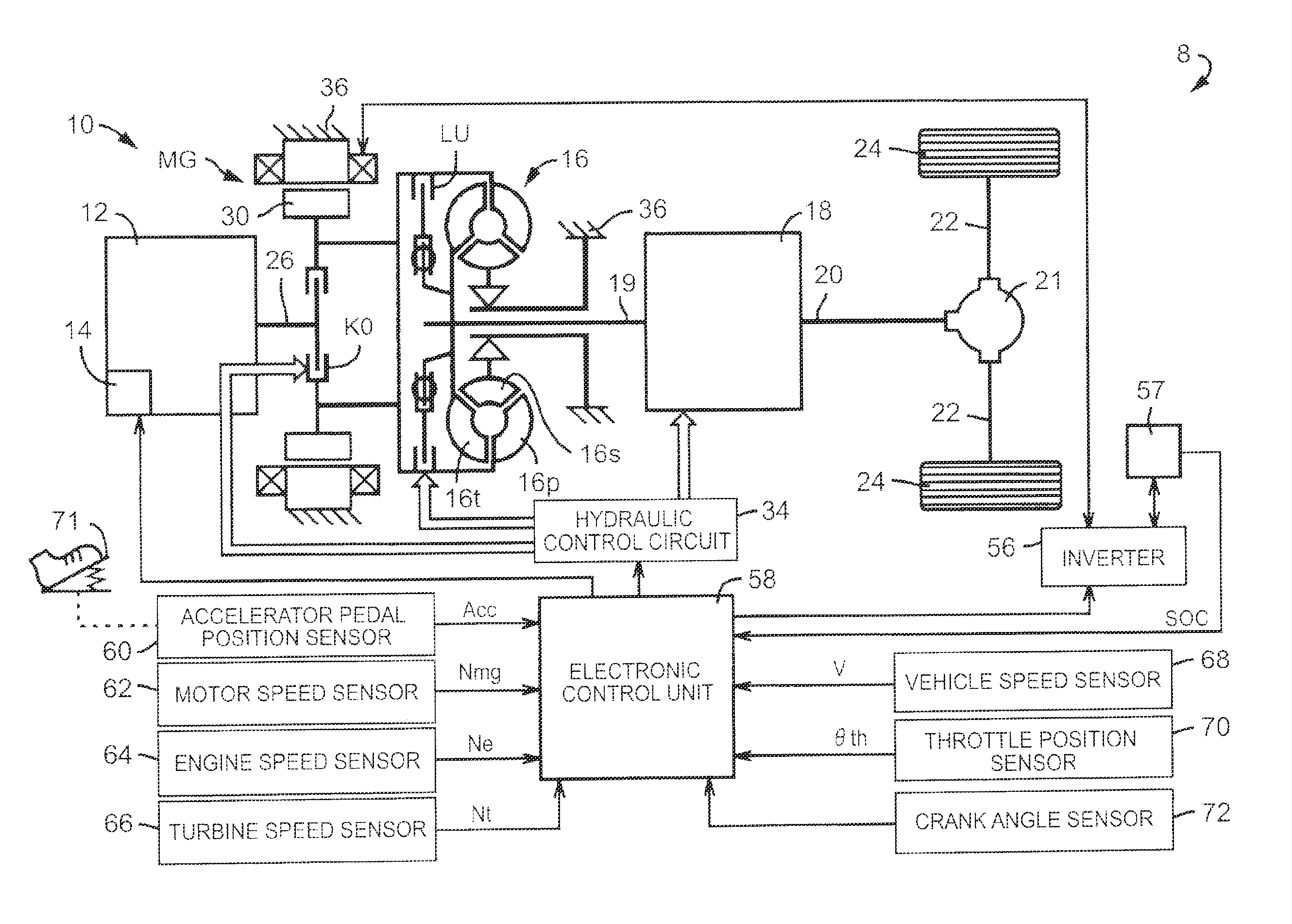
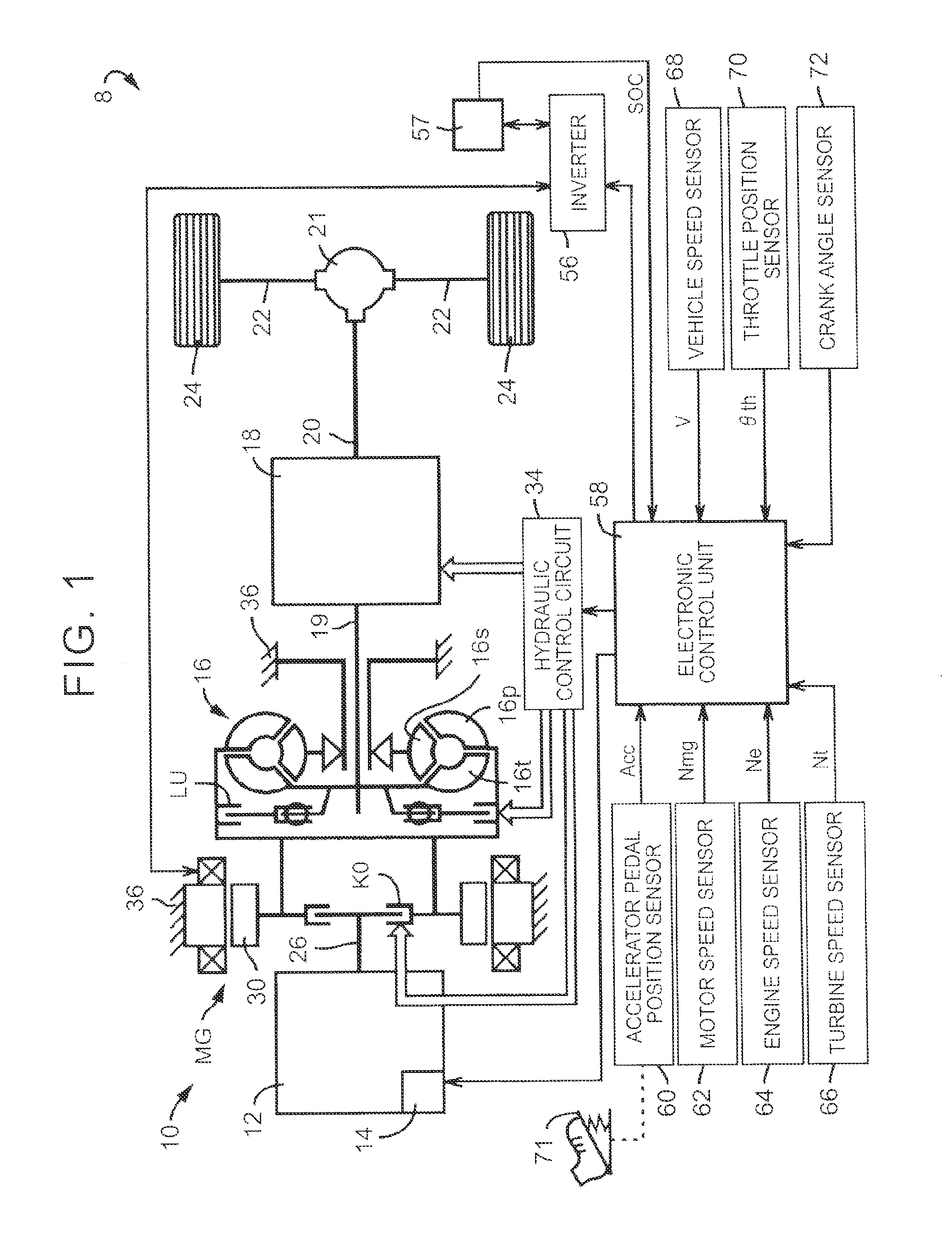
[0022]FIG. 1 schematically shows the construction of a driving system of a hybrid vehicle 8 (which will also be simply called “vehicle 8”) as one embodiment of the invention. The hybrid vehicle 8 includes a vehicular power train 10 (which will be called “power train 10”), a differential gear device 21, a pair of right and left axles 22, a pair of right and left driving wheels 24, a hydraulic control circuit 34, an inverter 56, and an electronic control unit 58. The power train 10 includes an engine 12 that functions as a source of driving power for running the vehicle, an engine output control unit 14 that performs engine output control, such as starting or stopping of the engine 12, or throttle control, an electric motor MG for running the vehicle, which functions as a source of driving power for running the vehicle, an engine coupling / decoupling clutch K0 corresponding to the clutch of...


PUM


Abstract

When an engine is started in a motor running mode, a control unit performs engine starting control by raising the engine speed through slip engagement of an engine coupling / decoupling clutch, temporarily reducing engaging force of the engine coupling / decoupling clutch after the engine becomes able to rotate by itself, and then fully engaging the engine coupling / decoupling clutch. The control unit advances the intake valve opening / closing timing at an earlier point in time as the motor speed is higher.

Description

INCORPORATION BY REFERENCE[0001]The disclosure of Japanese Patent Application No. 2012-204953 filed on Sep. 18, 2012 including the specification, drawings and abstract is incorporated herein by reference in its entirety.BACKGROUND OF THE INVENTION[0002]1. Field of the Invention[0003]The invention relates to a vehicle in which engine starting control is performed when an engine is started while the vehicle is running with power of a motor, and also relates to a control method for the vehicle.[0004]2. Description of Related Art[0005]A vehicle including an engine, a motor, and an engine clutch that selectively couples the engine to a power transmission path from the motor to driving wheels is known. A control system for this type of vehicle is disclosed in, for example, Japanese Patent Application Publication No. 2011-016390 (JP 2011-016390 A). The control system for the vehicle disclosed in JP 2011-016390 A performs engine starting control for temporarily releasing the engine clutch d...

Claims


Application Information

Patent Timeline
Patent Type & Authority Patents(United States)
IPC IPC(8): B60W10/02B60W10/06B60W10/08B60W20/00B60W30/18
CPCB60W20/40B60W30/18B60W10/02B60W10/08B60W10/06Y10S903/902B60K6/48B60W2710/023B60W2710/0605B60W2710/0644Y02T10/6221B60W2510/081B60W2710/025Y02T10/18Y02T10/6286Y10T477/26B60W2510/083B60W2510/0614B60W2510/0638B60W2710/081B60W2710/0616B60W2540/10B60W2520/10B60W2510/244Y02T10/62
Inventor NAKANISHI, NAOKIMATSUTANI, SHINTARO
Owner TOYOTA JIDOSHA KK
Learn More