
Control apparatus and control method for internal combusion engine

a control apparatus and control method technology, applied in the direction of electric control, machines/engines, output power, etc., can solve the problems deterioration of driveability, and achieve the effect of not increasing the range of deterioration of driveability

Inactive Publication Date: 2012-11-22
TOYOTA JIDOSHA KK
View PDF0 Cites 0 Cited by
  • Summary
  • Abstract
  • Description
  • Claims
  • Application Information

AI Technical Summary

Benefits of technology

[0011]The invention provides a control apparatus and a control method for an internal combustion engine that can perform a variable valve timing control when the engine is cold without increasing the range of deterioration in driveability.
[0014]On the other hand, when the control of increasing the fuel injection amount is being performed, the air-fuel ratio has been enriched through the control of increasing the fuel injection amount, and deterioration in driveability has already been caused. Thus, when the control of increasing the fuel injection amount is being performed, the variable valve timing control can be performed without the need of worrying that deterioration in driveability is caused. Further, since the fuel injection amount has been increased, the amount of burned fuel does not become insufficient during acceleration. Thus, according to the foregoing configuration, the variable valve timing control can be performed when the engine is cold, without increasing the range of the deterioration in driveability.
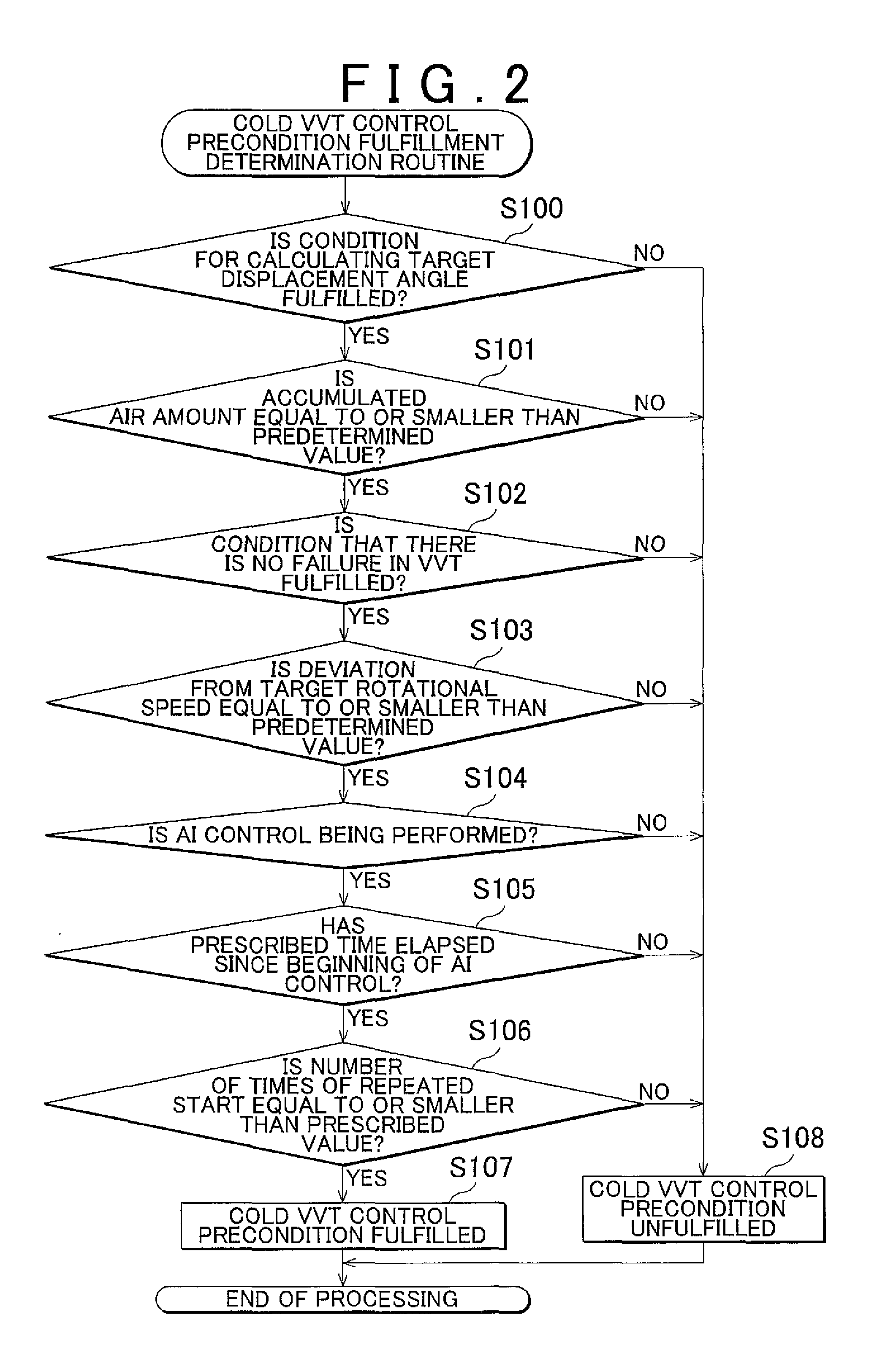
[0016]It should be noted that when the control of increasing the fuel injection amount and the variable valve timing control are started at the same time, the enrichment of the air-fuel ratio resulting from an increase in the fuel injection amount and the enrichment of the air-fuel ratio resulting from the advancement of the valve timing start simultaneously, and an abrupt increase in torque may be caused. Thus, the condition for performing the variable valve timing control when the engine is cold may include a condition that a prescribed time has elapsed since the beginning of the control of increasing the fuel injection amount. In this configuration, a time lag occurs between the beginning of the control of increasing the fuel injection amount and the beginning of the variable valve timing control. Thus, an abrupt increase in torque can be suppressed.
[0017]On the other hand, if the internal combustion engine is repeatedly started before the lapse of an engine stop time that is sufficient to evaporate the fuel that has adhered to the intake port, the amount of the fuel that has adhered to the intake port increases every time the internal combustion engine is started. Then, if the variable valve timing control is performed with an excessive amount of fuel adhering to the intake port when the engine is cold, the air-fuel ratio is greatly enriched, and a combustion failure may be caused. Thus, the condition for performing the variable valve timing control when the engine is cold may include a condition that the number of times of repeated start of the internal combustion engine is equal to or smaller than a prescribed value. In this configuration, if an excessive amount of fuel adheres to the intake port, the variable valve timing control is not permitted. Thus, the air-fuel ratio can be prevented from being greatly enriched through the performance of the variable valve timing control when the engine is cold.

Problems solved by technology

If the variable valve timing control is unconditionally performed when the engine is cold, the air-fuel ratio becomes rich due to the advancement of the valve timing, or the air-fuel ratio becomes lean during acceleration as described above, so that driveability may be deteriorated.
On the other hand, when the control of increasing the fuel injection amount is being performed, the air-fuel ratio has been enriched through the control of increasing the fuel injection amount, and deterioration in driveability has already been caused.

Method used


Image

  • Control apparatus and control method for internal combusion engine
  • Control apparatus and control method for internal combusion engine
  • Control apparatus and control method for internal combusion engine

Examples


Embodiment Construction

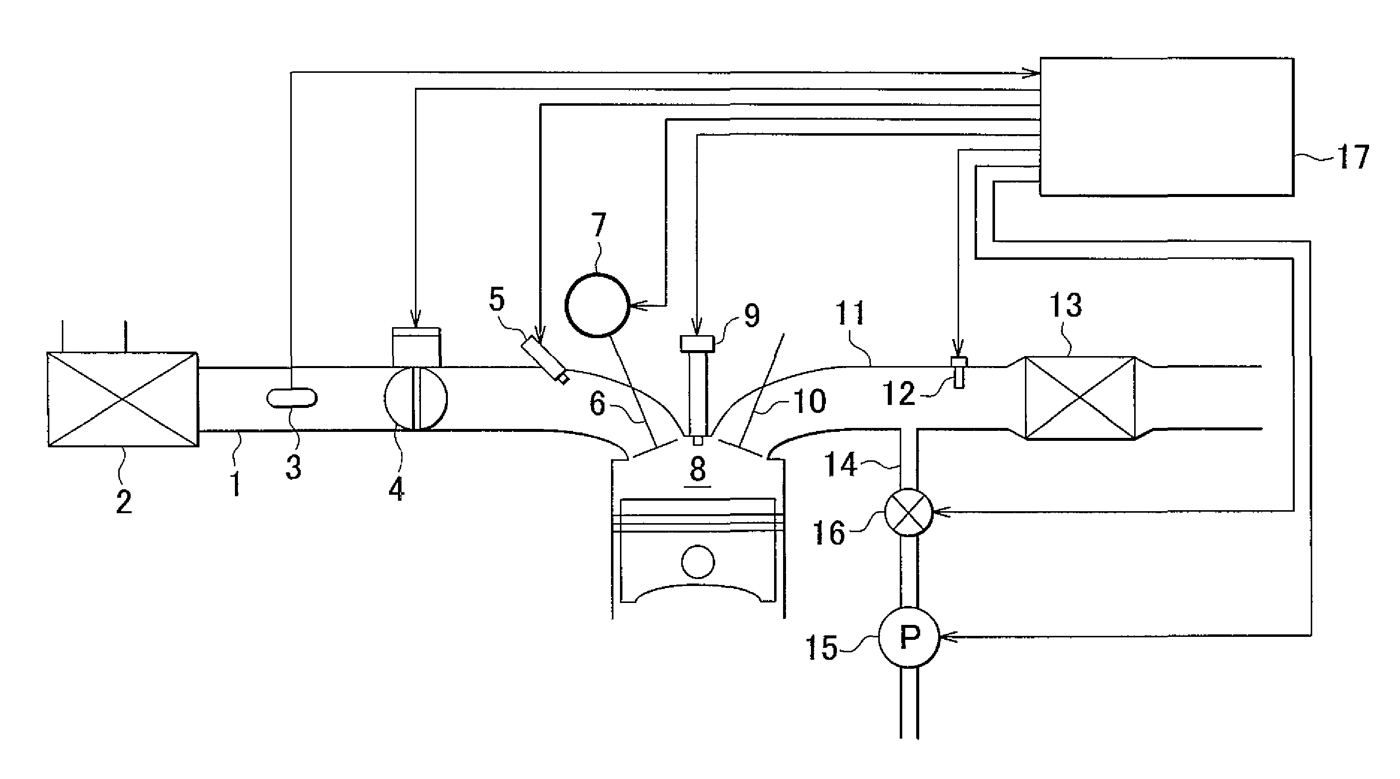
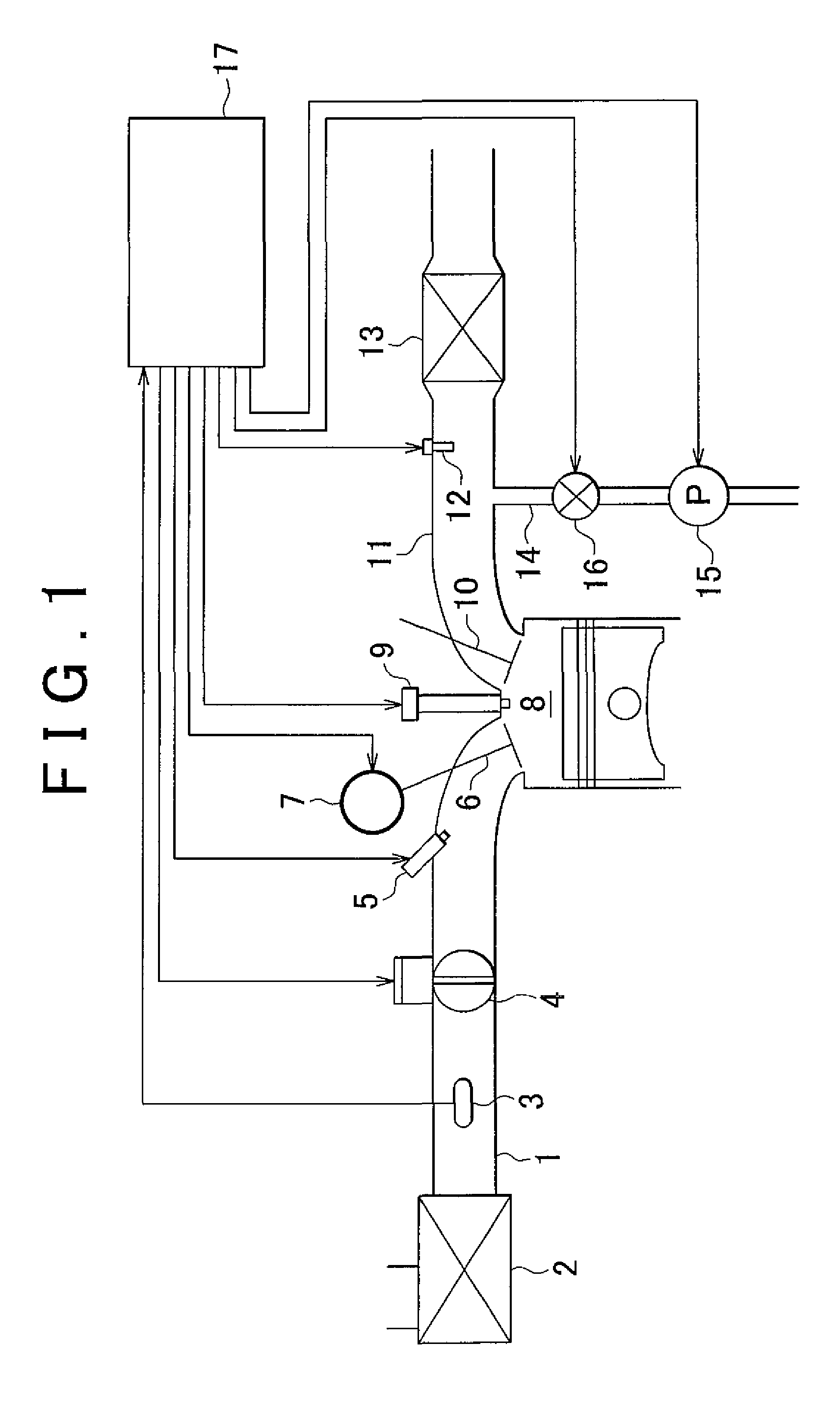
[0025]One embodiment of the invention as a concrete form of a control apparatus for an internal combustion engine according to the invention will be described hereinafter in detail with reference to FIGS. 1 to 5. As shown in FIG. 1, in an intake passage 1 of an internal combustion engine to which a control apparatus according to this embodiment of the invention is applied, an air cleaner 2 that purifies intake air, an airflow meter 3 that detects an amount of intake air, a throttle valve 4 that adjusts an amount of intake air, and an injector 5 that injects fuel into intake air are sequentially disposed from an upstream region of the intake passage 1. Besides, the intake passage 1 is connected to a combustion chamber 8 via an intake valve 6. It should be noted that this internal combustion engine is provided with a variable valve timing mechanism (a VVT mechanism) 7 that changes a valve timing of the intake valve 6.

[0026]An ignition plug 9 that ignites a mixture of intake air and fu...


PUM


Abstract

A control apparatus for an internal combustion engine includes a controller that performs a variable valve timing control to change a valve timing of an intake valve. A condition for performing the variable valve timing control when the engine is cold includes a condition that a control of increasing a fuel injection amount is being performed.

Description

INCORPORATION BY REFERENCE[0001]The disclosure of Japanese Patent Application No. 2011-112509 filed on May 19, 2011 including the specification, drawings and abstract is incorporated herein by reference in its entirety.BACKGROUND OF THE INVENTION[0002]1. Field of the Invention[0003]The invention relates to a control apparatus and a control method for an internal combustion engine that perform a variable valve timing control to change a valve timing of an intake valve.[0004]2. Description of Related Art[0005]A variable valve timing mechanism that changes the valve timing of an intake valve has been put into practical use as a mechanism that is mounted on an internal combustion engine installed in a vehicle or the like. In the internal combustion engine that is provided with this variable valve timing mechanism, a variable valve timing control that changes the valve timing of the intake valve in accordance with the engine operating state is performed.[0006]Conventionally, in Japanese ...

Claims


Application Information

Patent Timeline
IPC IPC(8): F01L1/34
CPCF02D41/047F02D41/06F02D41/064F01L2800/01F02D13/0203F01N3/22F02D2041/001
Inventor HIRAI, MAKIKOARIMA, TERUYOSHI
Owner TOYOTA JIDOSHA KK
Learn More