
Vehicle gear shift control device and gear shift control method

a control device and gear shift technology, applied in the direction of dynamo-electric gear control, road transportation, instruments, etc., can solve the problems deterioration of both fuel efficiency and driveability, and inhibit the deterioration of fuel efficiency resulting from the highest gear being maintained at high vehicle speed, so as to achieve the highest speed change ratio and inhibit the effect of deterioration of fuel efficiency

Active Publication Date: 2013-03-19
TOYOTA JIDOSHA KK
View PDF24 Cites 3 Cited by
  • Summary
  • Abstract
  • Description
  • Claims
  • Application Information

AI Technical Summary

Benefits of technology

[0006]The invention provides a vehicle speed change control device capable of inhibiting deterioration of fuel efficiency at high vehicle speeds exceeding a vehicle speed suitable for a speed change gear having the highest speed change ratio.
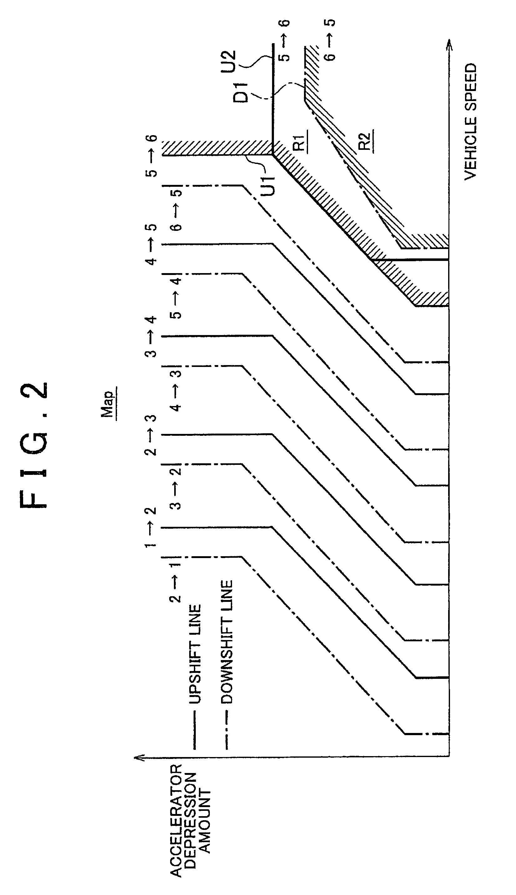
[0010]In the first aspect of the vehicle control device, the second shift line may be configured so that shifting to the prescribed gear based on the second shift line is inhibited or prohibited in the case where the vehicle speed is below a second prescribed vehicle speed. According to this aspect, since shifting to the prescribed gear is inhibited or prohibited in the case where the vehicle speed is below the second prescribed vehicle speed, by setting the second prescribed vehicle speed to a lower limit of vehicle speed at which improvement of fuel efficiency can be expected, unnecessary downshifting can be prevented and both improvement of fuel efficiency and inhibition or prohibition of deterioration of driveability can be realized. In this aspect, the second shift line may be such that the first low vehicle speed-low load portion extends toward the low load side. In this case, shifting to a prescribed gear based on the second shift line can be inhibited in regions below the second prescribed vehicle speed and below the second prescribed load. In this aspect, the second shift line may be such that the vehicle speed of the first low vehicle speed-low load portion is set to the second prescribed vehicle speed. In this case, shifting to a prescribed gear based on the second shift line can be prohibited in regions below the second prescribed vehicle speed and below the second prescribed load.
[0011]In the first aspect of the vehicle gear shift control device, a third shift line may be set in the shift map separately from the first shift line, the third shift line being used for realizing a shift pattern for shifting from the prescribed gear to the highest gear after shifting to the prescribed gear based on the second shift line, and being composed of a second high vehicle speed-high load portion with a vehicle speed equal to or greater than a fourth prescribed vehicle speed and with a load equal to or greater than a fourth prescribed load, a second low vehicle speed-low load portion with a vehicle speed equal to or less than a third prescribed vehicle speed lower than the fourth prescribed vehicle speed and with a load equal to or less than a third prescribed load lower than the fourth prescribed load, and a second intermediate portion located between the second high vehicle speed-high load portion and the second low vehicle speed-low load portion. In addition, in this aspect, the third shift line may be such that the second low vehicle speed-low load portion is located between the first shift line and the second shift line. According to this aspect, when vehicle speed decreases as a result of traveling by inertia (namely, during so-called coasting) while the load is maintained on the low load side equal to or less than the third prescribed load after having shifted to a prescribed gear based on the second shift line, shifting from a prescribed gear to the highest gear based on the third shift line is carried out since the third shift line crosses the second low vehicle speed-low load portion. Consequently, the rotating speed of the internal combustion engine can be reduced during coasting. As a result, fuel efficiency can be improved since so-called engine drag torque decreases. In addition, hysteresis is occurred since the second low vehicle speed-low load portion of the third shift line is separated from the second shift line in the direction in which vehicle speed changes. As a result, gear hunting can be prevented when shifting between a prescribed gear and the highest gear. In this aspect, the third shift line is such that the vehicle speed of the second low vehicle speed, low load portion may be set to the third prescribed vehicle speed.
[0012]In this aspect, the third shift line may be such that the second high vehicle speed-high load portion extends toward the high vehicle speed side. In this case, when the load has increased after having shifted the gear based on the second shift line, an operating state of the vehicle crosses the second high vehicle speed-high load portion of the third shift line, and the transmission is shifted from a prescribed gear to the highest gear based on the third shift line. Thus, the engine speed may be decreased more than in the case where a prescribed gear is maintained while the vehicle travels at high speed and under high load. Consequently, excessive rotation of the internal combustion engine at high vehicle speed and high loads can be prevented, and since fuel cutoff carried out during excessive rotation can be avoided by preventing this excessive rotation, deterioration of driveability can be prevented as a result of power performance being secured at high vehicle speeds and high loads. In addition, hysteresis is occurred since the second high vehicle speed-high load portion of the third shift line is separated from the second shift line in the direction in which the load changes. As a result, gear hunting during shifting between a prescribed gear and the highest gear can be prevented. In this aspect, the third shift line may be such that the load of the second high vehicle speed-high load portion is set to the fourth prescribed load.

Problems solved by technology

Thus, deterioration of fuel efficiency resulting from a highest gear being maintained at high vehicle speeds can be inhibited.
In the case where shifting to a prescribed gear based on the second shift line is not inhibited or prohibited in the case where acceleration is continued even after having shifted to the highest gear in the state in which the load has exceeded the first prescribed load, there is the possibility of deterioration of both fuel efficiency and driveability.

Method used


Image

  • Vehicle gear shift control device and gear shift control method
  • Vehicle gear shift control device and gear shift control method
  • Vehicle gear shift control device and gear shift control method

Examples


Embodiment Construction

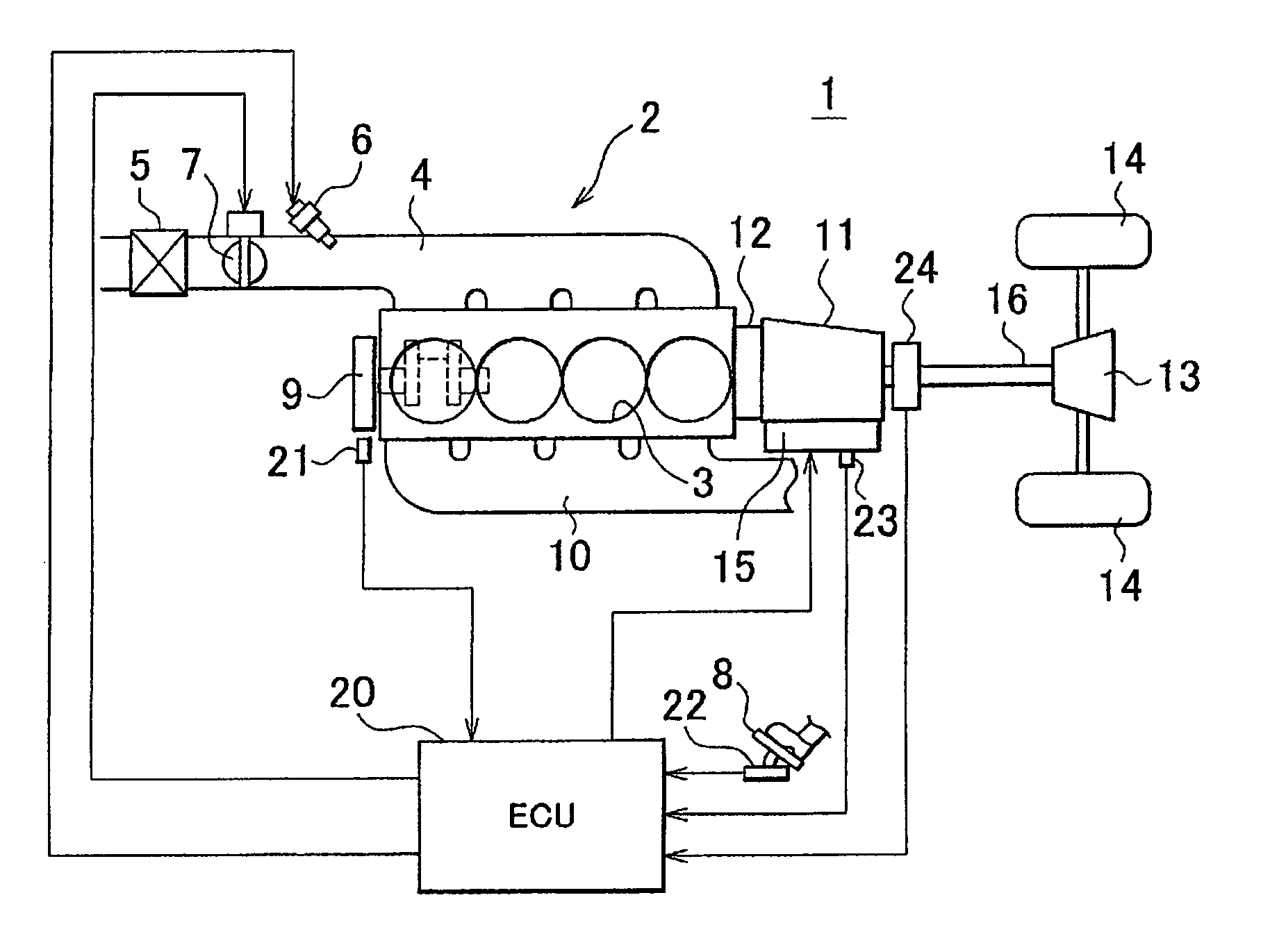
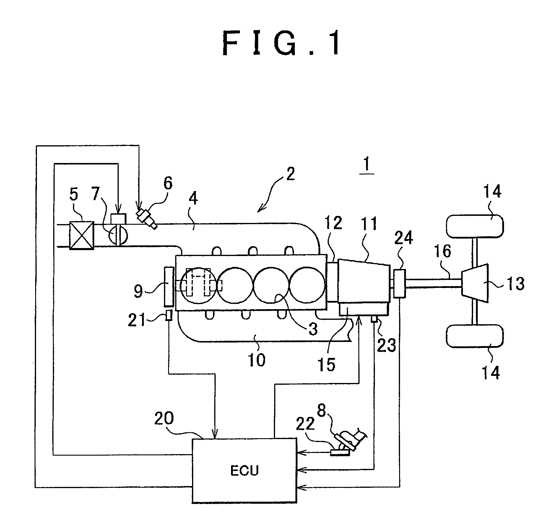
[0023]The following provides an explanation of the vehicle gear shift control device according to an embodiment of the invention. As shown in FIG. 1, a vehicle 1 is equipped with a motive power source such as an internal combustion engine 2. The internal combustion engine 2 according to the embodiment is an inline four-cylinder gasoline engine having four cylinders 3 arranged in a row. A fuel-air mixture, composed of a mixture of air filtered through an air filter 5 and fuel injected from a fuel injection valve 6, is introduced to each cylinder 3 through an intake passage 4. The intake air volume of the internal combustion engine 2 is adjusted with a throttle valve 7 provided in the intake passage 4, and the air-fuel ratio of the fuel-air mixture introduced into each cylinder 3 is adjusted to a prescribed air-fuel ratio by injecting the fuel through the fuel injection valve 6 in accordance with the intake air volume. The throttle valve 7 is operated to an opening that corresponds to...


PUM


Abstract

In a gear shift control device for a vehicle that shifts a transmission having a plurality of gears based on a shift line set in a shift map, an upshift line for shifting to the highest gear, and a downshift line that is located in a high vehicle speed region on the side of a higher vehicle speed than the upshift line are set in the shift map. The downshift line is used when shifting from the highest gear to a prescribed gear that has a larger gear ratio than the highest gear.

Description

BACKGROUND OF THE INVENTION[0001]1. Field of the Invention[0002]The invention relates to a vehicle gear shift control device and a gear shift control method applied to a transmission that is provided in a vehicle equipped with an internal combustion engine and is configured to be capable of shifting a plurality of gears having mutually different gear ratios.[0003]2. Description of the Related Art[0004]A conventional vehicle gear shift control device controls an automatic transmission having six forward gears based on shift maps in which shift lines are set for each shift pattern of the gears (see, for example, Japanese Patent Application Publication No. 2003-322249 (JP-A-2003-322249)).[0005]In the drive device of JP-A-2003-322249, in the case of having set the smallest sixth gear of a gear ratio (rotating speed of the input shaft of a transmission / rotating speed of the output shaft of a transmission) to an even smaller gear ratio in order to improve fuel efficiency, at high speeds e...

Claims


Application Information

Patent Timeline
Patent Type & Authority Patents(United States)
IPC IPC(8): G06F7/00
CPCF16H61/0213F16H2061/0234Y10T477/33F16H2061/0015F16H2061/0223Y02T10/76
Inventor IDESHIO, YUKIHIKOOKUWAKI, SHIGERUSHIBATA, HIROYUKIONO, TOMOHITO
Owner TOYOTA JIDOSHA KK
Learn More