Multi-mode wideband antenna

a wideband antenna and multi-mode technology, applied in the direction of elongated active element feed, resonant antenna, radiating element structure, etc., can solve the problem of unfavorable use in user devices

Inactive Publication Date: 2014-06-17
AMAZON TECH INC
View PDF5 Cites 38 Cited by
  • Summary
  • Abstract
  • Description
  • Claims
  • Application Information

AI Technical Summary

Problems solved by technology

These solutions are not conducive to use in user devices, often be...

Method used


Image

  • Multi-mode wideband antenna
  • Multi-mode wideband antenna
  • Multi-mode wideband antenna

Examples


Embodiment Construction

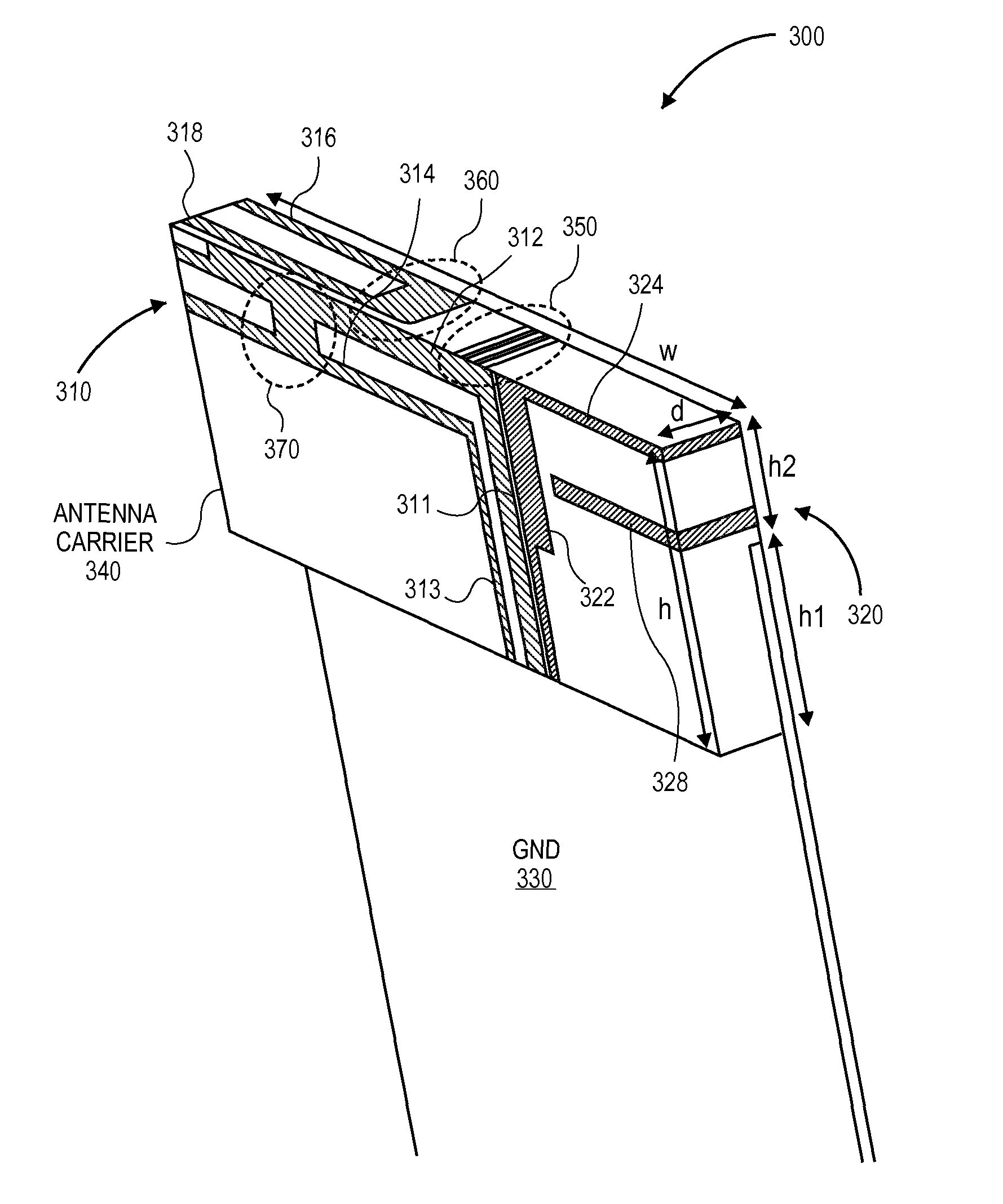
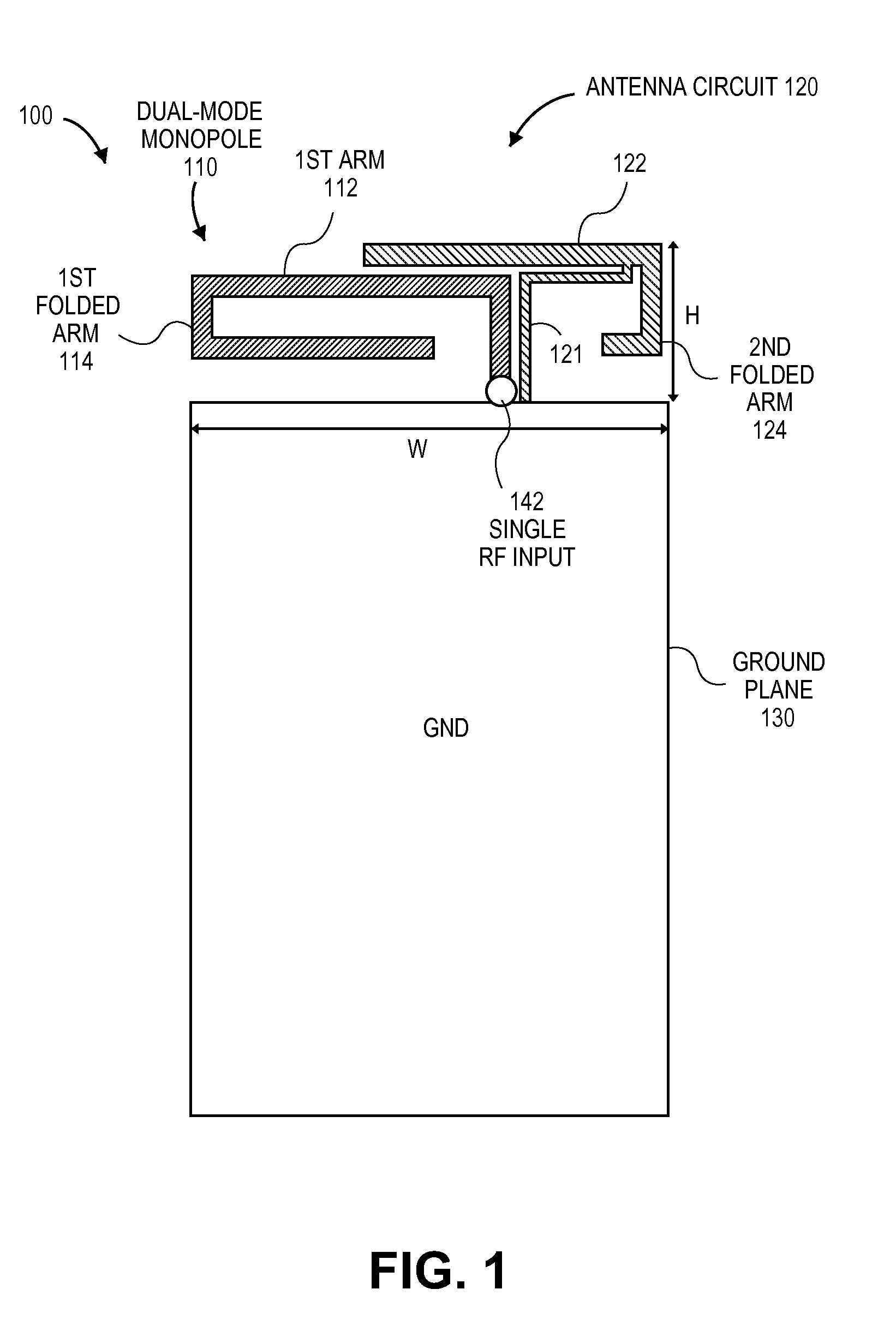
[0022]Methods and systems for extending a bandwidth of a multi-mode wideband antenna of a user device are described. A multi-mode wideband antenna includes a single radio frequency (RF) input coupled to a first antenna structure to provide a first resonant mode and a second resonant mode and to operate as a feeding structure to an antenna circuit that is not conductively coupled to the first antenna structure. The antenna circuit to provide additional resonant modes of the multi-mode wideband antenna. The user device may be any content rendering device that includes a wireless modem for connecting the user device to a network. Examples of such user devices include electronic book readers, portable digital assistants, mobile phones, laptop computers, portable media players, tablet computers, cameras, video cameras, netbooks, notebooks, desktop computers, gaming consoles, DVD players, media centers, and the like. The user device may connect to a network to obtain content from a server...


PUM


Abstract

Methods and systems for extending a bandwidth of a multi-mode wideband antenna of a user device are described. A multi-mode wideband antenna includes a single radio frequency (RF) input coupled to a first antenna structure to provide a first resonant mode and a second resonant mode and to operate as a feeding structure to an antenna circuit that is not conductively coupled to the first antenna structure. The antenna circuit is configured to provide additional resonant modes of the multi-mode wideband antenna.

Description

BACKGROUND OF THE INVENTION[0001]A large and growing population of users is enjoying entertainment through the consumption of digital media items, such as music, movies, images, electronic books, and so on. The users employ various electronic devices to consume such media items. Among these electronic devices (referred to herein as user devices) are electronic book readers, cellular telephones, personal digital assistants (PDAs), portable media players, tablet computers, netbooks, laptops, and the like. These electronic devices wirelessly communicate with a communications infrastructure to enable the consumption of the digital media items. In order to wirelessly communicate with other devices, these electronic devices include one or more antennas.[0002]The conventional antenna usually has only one resonant mode in the lower frequency band and one resonant mode in the high band. One resonant mode in the lower frequency band and one resonant mode in the high band may be sufficient to ...

Claims


Application Information

Patent Timeline
IPC IPC(8): H01Q1/24
CPCH01Q9/42H01Q1/243H01Q5/0058H01Q5/0062H01Q1/24H01Q5/371H01Q5/378
Inventor KUO, JERRY W.DRON, ANUJ
Owner AMAZON TECH INC
Why Eureka
Try Eureka