Supercharge Your Innovation With Domain-Expert AI Agents!

Reclosable multi zone isolation tool and method for use thereof

a multi-zone isolation and sleeve technology, applied in the direction of fluid removal, sealing/packing, borehole/well accessories, etc., can solve the problems of reducing the ultimate recovery of the well, reducing the ability to remove fluid from the high, and requiring an apparatus that does not allow fluid loss from the high pressure zone, so as to prevent the movement of the mandrel and the effect of preventing the shifting of the sleev

Active Publication Date: 2014-06-24
HALLIBURTON ENERGY SERVICES INC
View PDF8 Cites 4 Cited by
  • Summary
  • Abstract
  • Description
  • Claims
  • Application Information

AI Technical Summary

Benefits of technology

The present invention is an apparatus and method that allows for the isolation of separate zones in a wellbore without the need for delayed production from a lower pressure zone during production from a high pressure zone. It also enables simultaneous production from multiple zones without fluid loss from a high pressure zone into a lower pressure zone. A collet assembly is used to prevent shifting of the sleeve when in the open and closed positions, and a lock assembly is used to prevent movement of the mandrel in the second direction. A spring operated lug support prolapses the lug radially outwardly to create interference with the inner tubular, and a pressurization actuation chamber is used to release the lock assembly or apply pressure to actuate the apparatus. These features make the apparatus and method simple to use and efficient in producing oil and gas from multiple zones in a wellbore.

Problems solved by technology

It has been found, however, that this migration of hydrocarbons from one zone to another may decrease the ultimate recovery from the well.
It has been found, however, that from an economic perspective, delaying production from the lower pressure zone while only producing from the high pressure zone may be undesirable.
Further, a need has arisen for such an apparatus that does not allow fluid loss from a high pressure zone into a lower pressure zone if both zones are produced at the same time.

Method used


Image

  • Reclosable multi zone isolation tool and method for use thereof
  • Reclosable multi zone isolation tool and method for use thereof
  • Reclosable multi zone isolation tool and method for use thereof

Examples


Embodiment Construction

[0019]While the making and using of various embodiments of the present invention are discussed in detail below, it should be appreciated that the present invention provides many applicable inventive concepts, which can be embodied in a wide variety of specific contexts. The specific embodiments discussed herein are merely illustrative of specific ways to make and use the invention, and do not delimit the scope of the present invention.

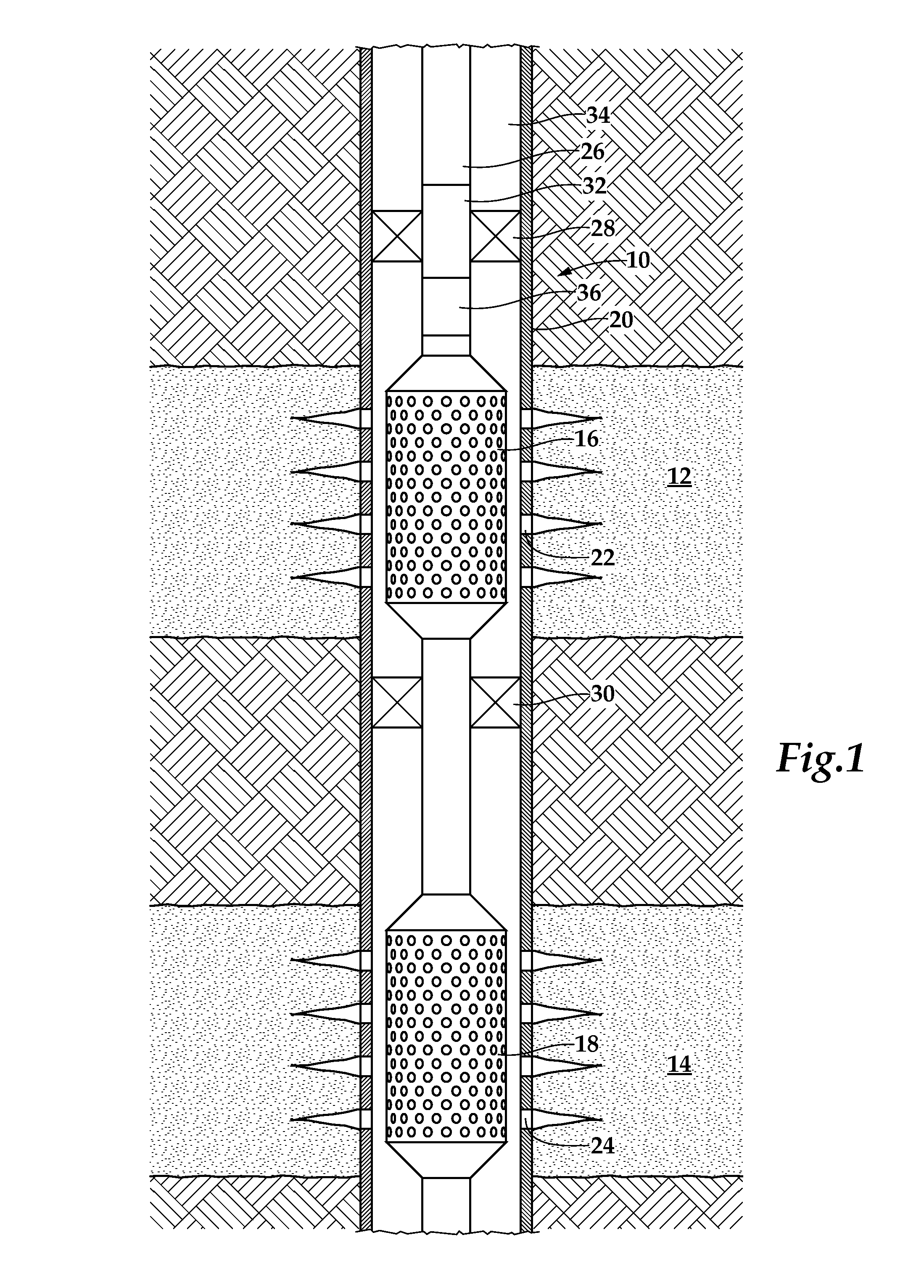
[0020]The present invention provides improved methods and tools for completing and separately producing individual hydrocarbon zones in a single well. The methods can be performed in either vertical or horizontal wellbores. The term “vertical wellbore” is used herein to mean the portion of a wellbore in a producing zone, which is substantially vertical, inclined or deviated. The term “horizontal wellbore” is used herein to mean the portion of a wellbore in a producing zone, which is substantially horizontal. Since the present invention is applicable in...


PUM


Abstract

An apparatus for isolating a first zone from a second zone in a subterranean wellbore. The apparatus includes an outer tubular and an inner tubular disposed within the outer tubular forming an annular flow path therebetween that is in fluid communication with the first zone. The inner tubular defines a central flow path that is in fluid communication with the second zone. A sleeve having at least one seal is positioned in the annular flow path and is axially movable relative to the inner and outer tubulars between a closed position wherein the seal engages the inner tubular and an open position wherein the seal engages the outer tubular. A mandrel is slidably disposed within the inner tubular and is coupled to the sleeve. The mandrel is operable to shift the sleeve between the open position and the closed position responsive to changes in pressure within the central flow path.

Description

TECHNICAL FIELD OF THE INVENTION[0001]This invention relates, in general, to equipment utilized in conjunction with operations performed in subterranean wells and, in particular, to a reclosable multi zone isolation tool for isolating an upper zone from a lower zone in a subterranean wellbore and a method for use thereof.BACKGROUND OF THE INVENTION[0002]Without limiting the scope of the present invention, its background will be described with reference to producing multiple hydrocarbon bearing subterranean zones in a well, as an example.[0003]It is common to encounter hydrocarbon wells that traverse more than one separate subterranean hydrocarbon bearing zone. In such wells, the separate subterranean hydrocarbon bearing zones may have similar or different characteristics. For example, the separate subterranean hydrocarbon bearing zones may have significantly different formation pressures. Even with the different pressures regimes, it may nonetheless be desirable to complete each of ...

Claims


Application Information

Patent Timeline
Patent Type & Authority Patents(United States)
IPC IPC(8): E21B34/10E21B34/00
CPCE21B34/10E21B33/127E21B34/102E21B34/107E21B43/14E21B43/25
Inventor SCOTT, KEITH WAYNEHENDERSON, WILLIAM DAVIDSCHAFER, DOUGLAS ALLEN
Owner HALLIBURTON ENERGY SERVICES INC
Features
  • R&D
  • Intellectual Property
  • Life Sciences
  • Materials
  • Tech Scout
  • Unparalleled Data Quality
  • Higher Quality Content
  • 60% Fewer Hallucinations
Learn More