
Proximity sensor and portable terminal

a proximity sensor and portable terminal technology, applied in the field of proximity sensors, can solve the problems of difficult space security, proximity sensor may improperly recognize that there is an object in proximity, and the touch screen is not intended, so as to prevent an improper action of the proximity sensor

Inactive Publication Date: 2014-06-24
SONY CORP
View PDF4 Cites 5 Cited by
  • Summary
  • Abstract
  • Description
  • Claims
  • Application Information

AI Technical Summary

Benefits of technology

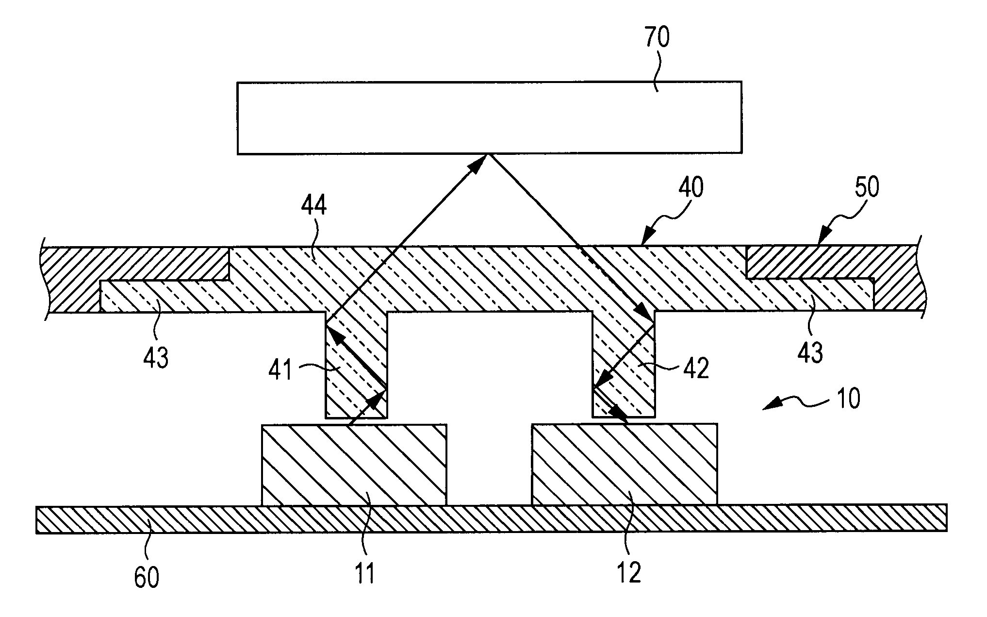
[0017]According to the proximity sensor structured in accordance with the embodiment of the present disclosure, it is possible to prevent an improper action of the proximity sensor, even in the case where the proximity sensor has a large window thickness, without increasing the number of components or the area for installation of the light emitting section / light receiving section.

Problems solved by technology

However, such a contact with the touch screen is not intended by the user to be performed on the touch screen.
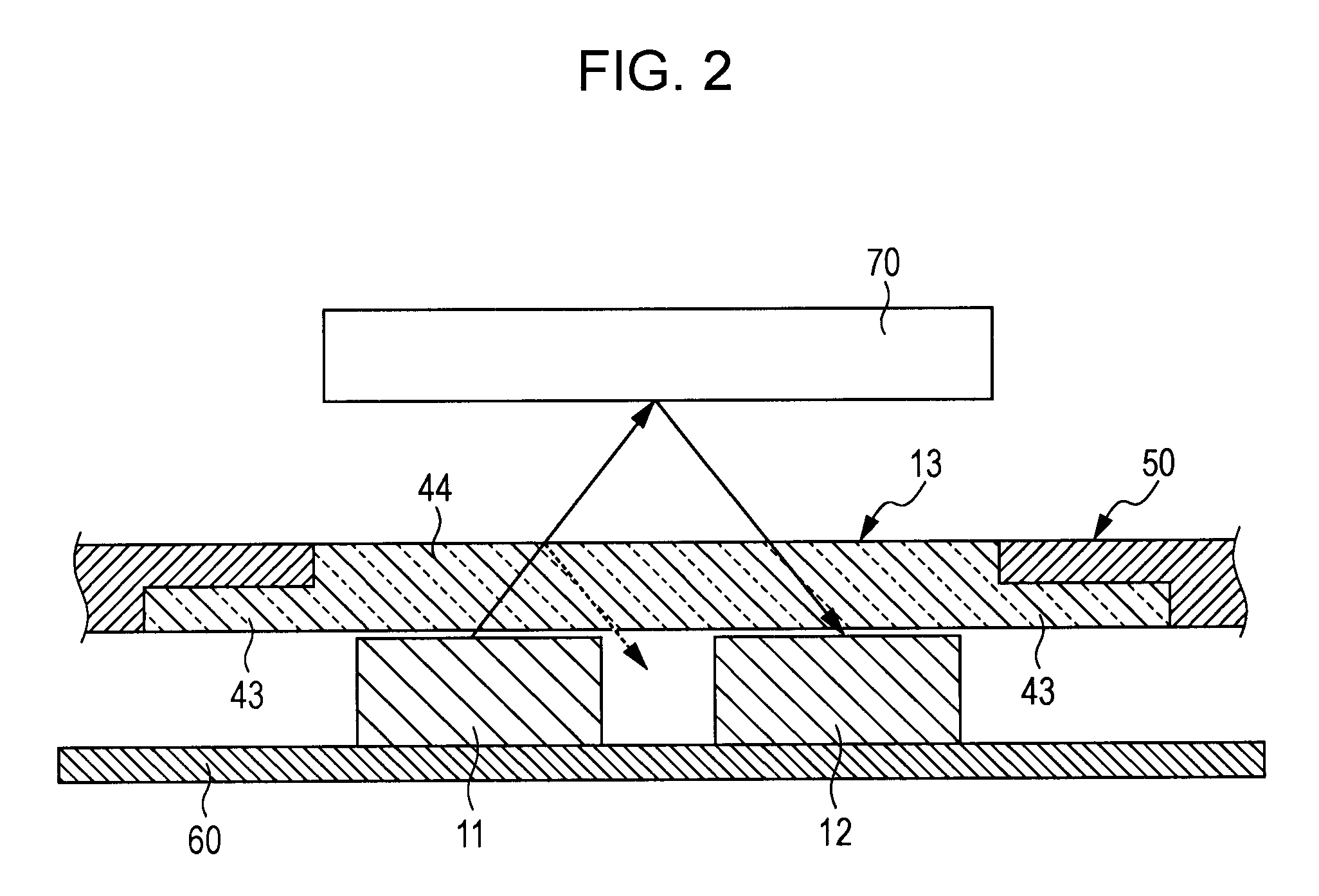
In this case, the proximity sensor may improperly recognize that there is an object in proximity even if there is no such object in proximity to the proximity sensor.
In that case, however, it may be difficult to secure a space that allows the light emitting section and the light receiving section to be sufficiently separated from each other in the portable terminal because of a reduced size of the terminal.
In this case, however, the distance over which an object in proximity is recognizable may be reduced, and the performance of the proximity sensor may not be satisfactory.
However, the device according to the related art includes a large number of components forming the window member, which complicates the manufacture and increases the cost.

Method used


Image

  • Proximity sensor and portable terminal
  • Proximity sensor and portable terminal
  • Proximity sensor and portable terminal

Examples


Embodiment Construction

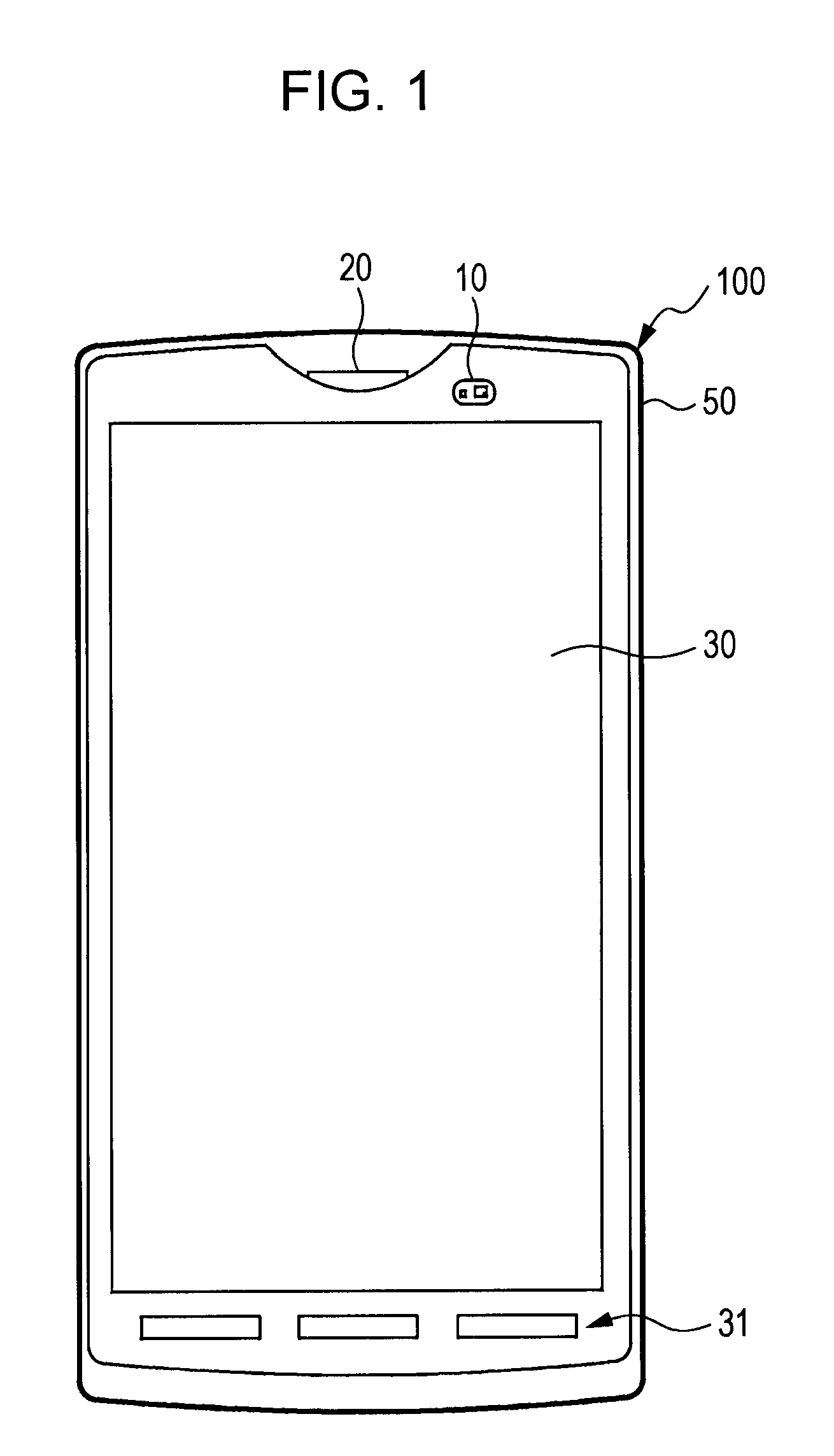
[0026]FIG. 1 shows an example of a portable terminal 100 including a proximity sensor 10 according to the embodiment. The portable terminal 100 includes a display section 30 forming a touch screen disposed on the front surface of a housing 50. The display section 30 is formed by a liquid crystal display, for example. A touch area that detects a touch by a finger of a user, a pen, or the like is provided to overlap a display area of a display screen of the display section 30. Also on the front surface of the housing 50, a receiver sound hole 20 is disposed at the center of the upper part of the display section 30. The proximity sensor 10 is disposed next to the receiver sound hole 20. An operating section 31 such as operating keys is disposed at the lower part of the front surface of the housing 50.

[0027]The proximity sensor 10 is an element for detection of an approaching state of an object. Specifically, when the user holds the housing 50 and brings the receiver sound hole 20 close...


PUM


Abstract

A proximity sensor that includes a light emitting section that emits light; a light receiving section that detects the light emitted from the light emitting section reflected from an object; a window member that covers the light emitting section and the light receiving section; a first columnar portion disposed to extend between the light emitting section and the window member; and a second columnar portion disposed to extend between the light receiving section and the window member.

Description

CROSS REFERENCE TO RELATED APPLICATION[0001]The present application claims the benefit of the earlier filing date of U.S. Provisional Patent Application Ser. No. 61 / 452,903 filed on Mar. 15, 2011, the entire contents of which is incorporated herein by reference.BACKGROUND OF THE DISCLOSURE[0002]1. Field of the Disclosure[0003]The present disclosure relates to a proximity sensor for detection of an approaching state of an object, and in particular to a proximity sensor that is suitable for application to a portable terminal.[0004]2. Description of Related Art[0005]In recent years, portable terminals called “smartphones” have been widely used. In many smartphones, a touch screen in which a display screen also serves as a touch panel is used. When a user brings his / her ear close to a sound output port of an ear receiver provided at a predetermined location of a housing of such a portable terminal during a conversation or the like, the face or the ear of the user may contact the touch s...

Claims


Application Information

Patent Timeline
Patent Type & Authority Patents(United States)
IPC IPC(8): H04M1/00
CPCH03K17/941H03K2217/94108
Inventor KIDO, NOBUHIKO
Owner SONY CORP
Learn More