Structured light for 3D shape reconstruction subject to global illumination

a technology of structured light and 3d shape reconstruction, applied in the direction of image analysis, image enhancement, instruments, etc., can solve problems such as degrading the performance of such methods

Active Publication Date: 2014-08-19
MITSUBISHI ELECTRIC RES LAB INC
View PDF16 Cites 38 Cited by
  • Summary
  • Abstract
  • Description
  • Claims
  • Application Information

AI Technical Summary

Benefits of technology

[0016]We provide methods for detecting residual errors and correcting the errors by acquiring a small number of additional images. Our methods do not require an explicitly separation of the global and direct components of illumination, as in the prior art. Consequently, we can handle a larger class of scenes, while requiring fewer images when compared to conventional explicit methods.

Problems solved by technology

Consequently, global light transport (GLT) effects, such as inter-reflections, diffusion, subsurface and volumetric scattering and translucency severely degrade the performance of such methods.

Method used


Image

  • Structured light for 3D shape reconstruction subject to global illumination
  • Structured light for 3D shape reconstruction subject to global illumination
  • Structured light for 3D shape reconstruction subject to global illumination

Examples


Embodiment Construction

[0019]Error Analysis for Structured-Light Under Global Light Transport

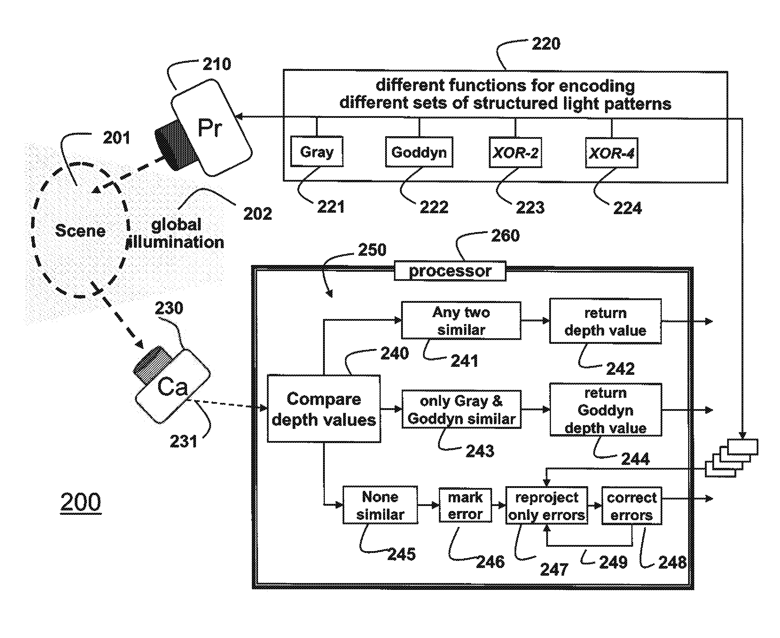
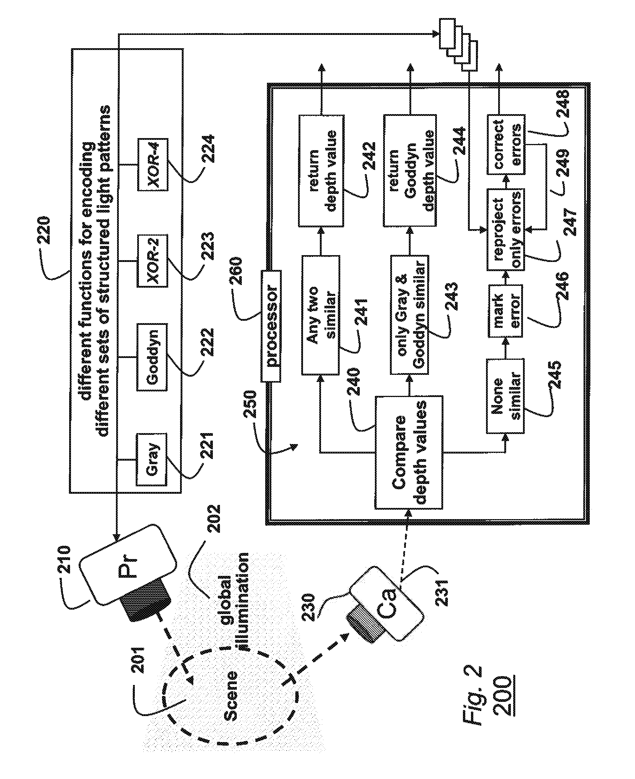
[0020]The basic principle behind shape from structured light methods is triangulation. Each row and column of pixels in a projector is encoded with unique spatial or temporal codes to form structured light patterns. The projector illuminates the scene with the light pattern, while a camera acquires a sequence of images, one for each pattern.

[0021]For each pixel in the camera sensor, the corresponding row and column of the projector are determined by decoding measured intensity values. Then, depths are determined by triangulating camera rays and a projector plane. For correct decoding, it is assumed that each camera pixel receives irradiance from a single projector pixel.

[0022]However, in most real world scenes, the camera pixel can receive irradiance from multiple projector pixels due to global light transport effects, camera / projector defocus and optics artifacts, spatial misalignment of projector-camera pixels, ...


PUM


Abstract

Depth values in a scene are measured by projecting sets of patterns on the scene, wherein each set of patterns is structured with different spatial frequency using different encoding functions. Sets of images of the scene is acquired, wherein there is one image for each pattern in each set. Depth values are determining for each pixel at corresponding locations in the sets of images. The depth values of each pixel are analyzed, and the depth value is returned if the depth values at the corresponding locations are similar. Otherwise, the depth value is marked as having an error.

Description

FIELD OF THE INVENTION[0001]This invention relates generally to measuring depth values in scenes using structured light patterns, and more particularly to measuring shapes in scenes subject to global illumination.BACKGROUND OF THE INVENTION[0002]Structured light triangulation is a method of choice for measuring shape in applications, including industrial automation, computer graphics, virtual reality, robot-human interaction, medical surgery, and computer vision. The shapes are measured from depth values.[0003]Work in this field has been driven by two factors: first, reducing acquisition time, and second, increasing depth resolution. Conventional methods can measure 3D shapes at close to 1000 Hz with a depth resolution of more than 30 microns.[0004]Most structured light methods make an important assumption: a scene only receives illumination directly from a light source. This assumption can only be fulfilled in a controlled laboratory or studio setting. For most real world scenes, t...

Claims


Application Information

Patent Timeline
Patent Type & Authority Patents(United States)
IPC IPC(8): G06K9/40G06T7/00
CPCG06T7/0057G06T2207/10152G06T2207/20221G06T7/521
Inventor VEERARAGHAVAN, ASHOKGUPTA, MOHITAGRAWAL, AMIT
Owner MITSUBISHI ELECTRIC RES LAB INC
Why Eureka
Try Eureka