Three-dimensional video scanner

a three-dimensional video and scanning technology, applied in the direction of instruments, electric discharge lamps, geological measurements, etc., can solve the problems of high cost, significant inaccuracy, and inability to meet real-time operation, and achieve the effect of reducing the cost of 3dv-system products, high precision, and high accuracy

Active Publication Date: 2007-07-19
TECHNION RES & DEV FOUND LTD +1
View PDF4 Cites 46 Cited by
  • Summary
  • Abstract
  • Description
  • Claims
  • Application Information

AI Technical Summary

Problems solved by technology

It is clear that the approach is not suitable for real time operation.
However, texture within the object may cause matching problems and significant inaccuracies.
The 3DV-systems products require very high precision and are thus very expensive.

Method used


Image

  • Three-dimensional video scanner
  • Three-dimensional video scanner
  • Three-dimensional video scanner

Examples


Embodiment Construction

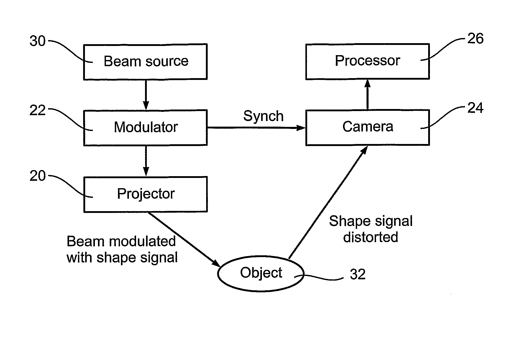
[0066] The present embodiments comprise an improved solution that comes under the structured light heading described above. The solution is based on a recent nano-technology development in the projection field that allows the classical coded light technique to work in real time, together with a modification of existing CMOS sensing technology. The idea is to use the nano-technology to project a sequence of binary patterns efficiently at very high frame rate onto an object whose three-dimensional contour information is required. The pattern strikes the object and is distorted. Subsequently the distorted binary pattern sequence arriving at the imaging sensor is detected at each pixel thereof. The disparity between the sent and received pixels may then be computed to yield the 3D shape of the object. In order to achieve real time processing, the sensor does not attempt to transmit all of the information received at each pixel. Rather, since the original coded image comprises binary pat...


PUM


Abstract

A 3D scanning device comprises: a digital light encoding unit comprising a digital micromirror device for encoding a rapidly changing shape signal onto a light beam directed to an object, a shape of said signal being selected such that distortions thereof by a contoured object reveal three-dimensional information of said contour; a detector synchronized with said digital light processing unit for detecting reflections of said light beam from said object, and a decoder for determining a 3D shape of said object from distortions of said signal in said detected reflections.

Description

FIELD AND BACKGROUND OF THE INVENTION [0001] The present invention relates to a method and apparatus for three dimensional video sampling or scanning and, more particularly, but not exclusively to a method or apparatus for obtaining scanning data in real time. [0002] There are many ways to scan the 3D shape of objects, and some of these methods have been in use for many years. One such method is to obtain shape information from shading, but this requires prior knowledge of how the object is lit. A method that has been in use for many years is shape from stereo, which involves using two cameras to photograph an object. A further method is to obtain the shape from photometric stereo. Photometric stereo uses successive images taken from the same camera position but under different lighting conditions. [0003] A further technique is illustrated in appended FIGS. 1a) and 1b) and obtains shape from structured light. Briefly the technique involves constructing a surface model of an object b...

Claims


Application Information

Patent Timeline
Patent Type & Authority Applications(United States)
IPC IPC(8): G01B11/24G01B11/25G06K9/00
CPCG01B11/2513
Inventor KIMMEL, RON
Owner TECHNION RES & DEV FOUND LTD
Why Eureka
Try Eureka