
Air break electrical switch having a blade open/closed indicator

a technology of air break and indicator, which is applied in the direction of air break switches, switches with movable electrical contacts, electrical equipment, etc., can solve the problems of damage to the contact surface of the blade, difficulty for an operator standing on the ground to observe longitudinal rotation of the blade, and difficulty in determining if the blade has established a proper electrical connection with the electrical terminal

Active Publication Date: 2014-09-09
HUBBELL POWER SYST INC
View PDF12 Cites 18 Cited by
  • Summary
  • Abstract
  • Description
  • Claims
  • Application Information

AI Technical Summary

Benefits of technology

The present invention provides an air break electrical switch that includes a first electrical terminal, a second electrical terminal, a blade support, and an indicator. The switch can be opened and closed to electrically connect the two terminals by pivoting the blade from an open position to a closed position. The indicator is fixed to the blade or the blade support and can display a color to indicate the position of the blade. The blade is supported by the blade support and can be opened and closed as needed. The switch provides an improved safety and reliability, as it prevents accidental contact with electrical terminals when the switch is in an open position.

Problems solved by technology

Depending on the voltage difference between the blade and the electrical terminal, electrical arcing can occur and potentially damage contact surfaces of the blade and the electrical terminal if the blade moves slightly out of contact with the terminal.
However, it can be difficult for an operator standing on the ground to observe longitudinal rotation of the blade even if the switch is mounted at a relatively low height on a utility structure.
As such, it can be difficult to determine if the blade has established a proper electrical connection with the electrical terminal.
If the blade does not properly engage the electrical terminal, potentially-damaging arcing can occur as described above.

Method used


Image

  • Air break electrical switch having a blade open/closed indicator
  • Air break electrical switch having a blade open/closed indicator
  • Air break electrical switch having a blade open/closed indicator

Examples


Embodiment Construction

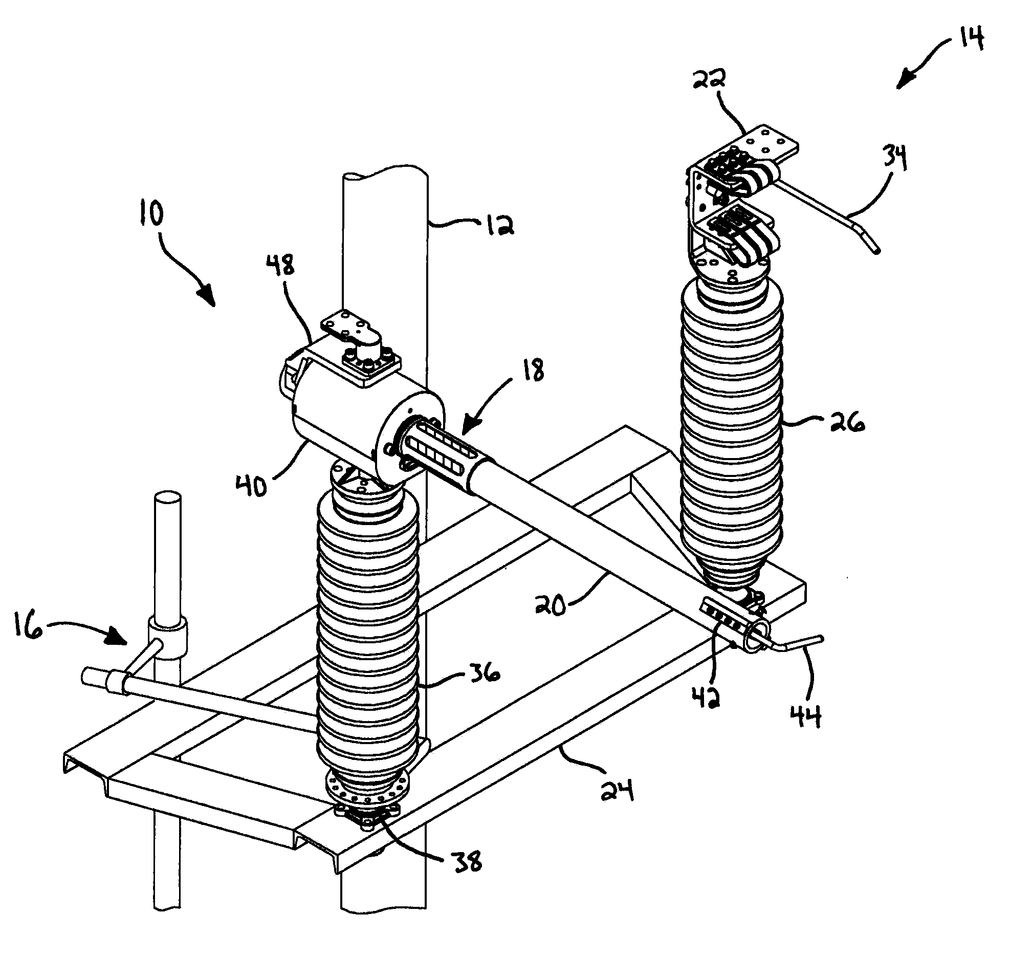
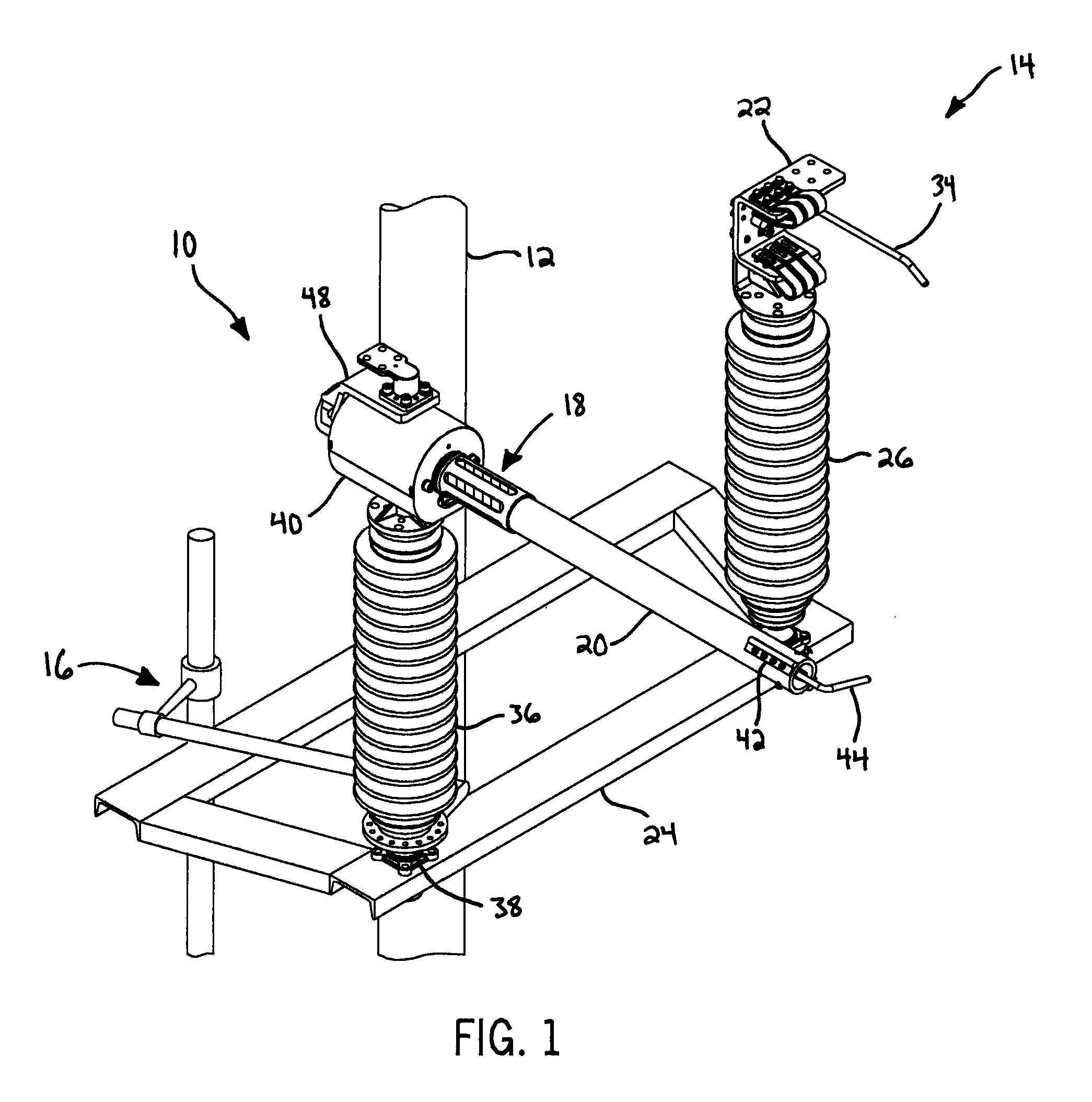
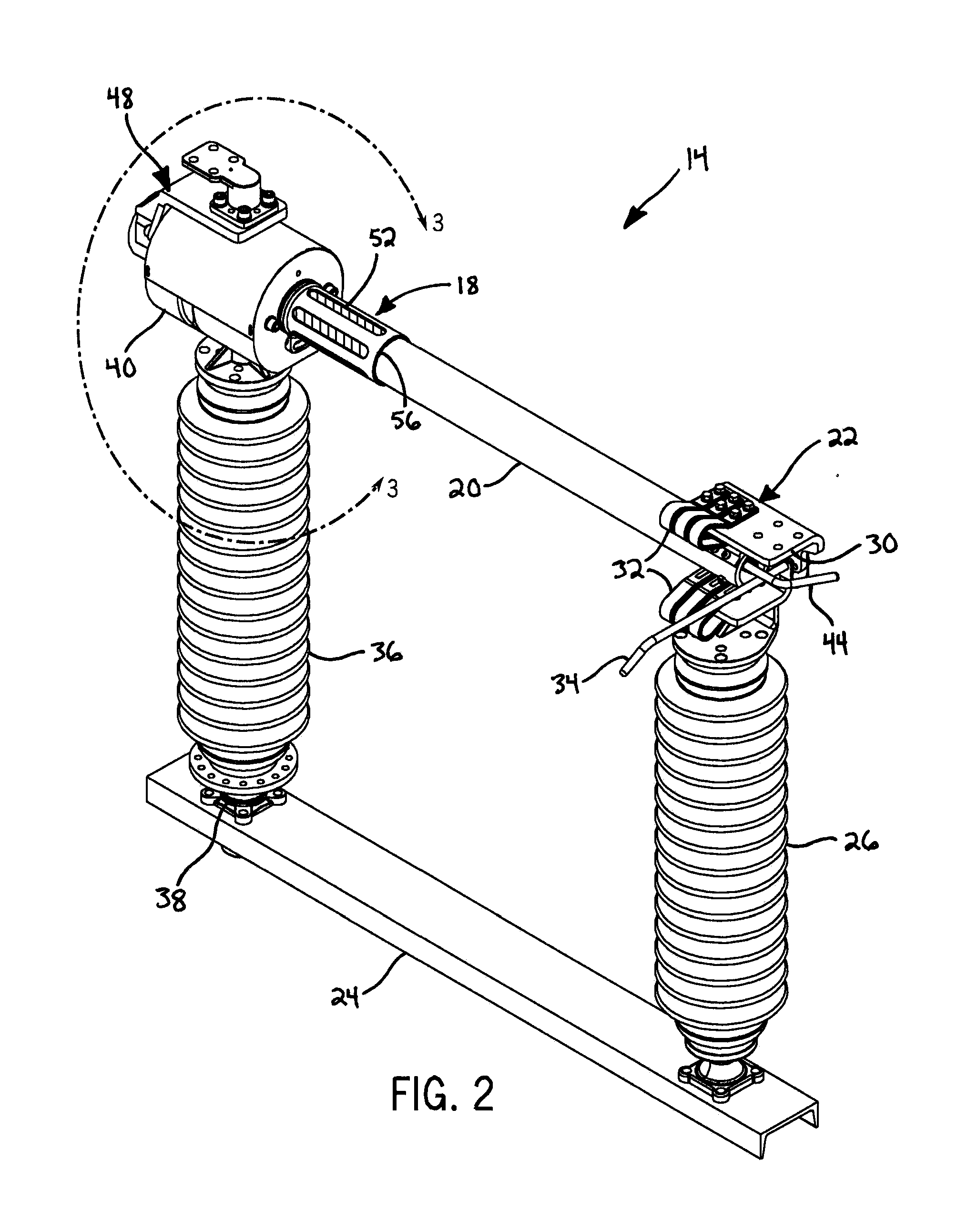
[0022]Referring first to FIG. 1, a high voltage / high current electrical or air break switch 10 of the present invention may be supported by various types of appropriate utility structures, such as a simple elongated utility pole 12. The switch 10 includes one or more upper switches 14 disposed above the ground and an operating mechanism 16 extending from the upper switch 14 toward the ground. The operating mechanism 16 may be driven by an electrical technician on the ground to move the upper switch 14 between different operating positions. Unlike previous designs, the present switch 10 includes an open / closed indicator assembly 18 that indicates whether an electrically conductive blade 20 is in proper engagement with a distal electrical terminal 22. These aspects are described in further detail in the following paragraphs, beginning with a general description of the upper switch 14 and concluding with a description of the indicator assembly 18.

[0023]Referring now to FIGS. 1-4, the u...


PUM


Abstract

An air break electrical switch includes a first electrical terminal and a second electrical terminal supported apart from the first electrical terminal. The switch further includes a blade support configured to be electrically insulatively supported apart from the second electrical terminal. A blade is pivotally supported by the blade support, and the blade is pivotable from an open contact position to a closed contact position and vice versa. The switch further includes an indicator connected to the blade. At least a portion of the indicator is fixed to the blade so as to rotate with the blade and display a first color when the blade is in the open contact position and obscure the first color when the blade is in the closed contact position.

Description

CROSS-REFERENCE TO RELATED APPLICATION[0001]This application claims the benefit of U.S. Provisional Patent Application No. 61 / 449,444 filed Mar. 4, 2011, the disclosure of which is hereby incorporated by reference for all purposes.STATEMENT CONCERNING FEDERALLY SPONSORED RESEARCH OR DEVELOPMENT[0002]Not applicable.FIELD OF THE INVENTION[0003]This invention relates to high voltage / high current air break switches, particularly switches that indicate whether a pivotable blade is in an open or closed position.BACKGROUND OF THE INVENTION[0004]High voltage / high current air break switches typically include an elongated conductive contact or “blade” that engages an electrical terminal to establish an electrical connection. Depending on the voltage difference between the blade and the electrical terminal, electrical arcing can occur and potentially damage contact surfaces of the blade and the electrical terminal if the blade moves slightly out of contact with the terminal. As such, some prev...

Claims


Application Information

Patent Timeline
Patent Type & Authority Patents(United States)
IPC IPC(8): H01H31/00
CPCH01H31/00H01H9/16H01H31/28H01H1/42
Inventor RHEIN, DAVID, A.
Owner HUBBELL POWER SYST INC
Learn More