
Syncronized patient elevation and positioning apparatus positioning support systems

a positioning support system and patient technology, applied in the field of patient elevation and positioning apparatus, can solve the problems of difficult positioning procedures and compromise of surgical si

Active Publication Date: 2014-09-30
WARSAW ORTHOPEDIC INC
View PDF79 Cites 86 Cited by
  • Summary
  • Abstract
  • Description
  • Claims
  • Application Information

AI Technical Summary

Benefits of technology

The apparatus streamlines patient positioning, reducing procedural interruptions and enhancing surgical access by allowing smooth transitions between supine and prone positions, thus improving operational efficiency and patient safety during surgeries.

Problems solved by technology

Such transfer procedures interrupt the surgical procedure, are cumbersome, and may compromise the surgical site.
Since the patient begins in a supine position on a gurney, also referred to as a trolley or a stretcher, and must be transferred to a prone position on an open frame patient support structure, such positioning procedures can be quite difficult.

Method used


Image

  • Syncronized patient elevation and positioning apparatus positioning support systems
  • Syncronized patient elevation and positioning apparatus positioning support systems
  • Syncronized patient elevation and positioning apparatus positioning support systems

Examples


Embodiment Construction

[0036]As required, detailed embodiments of the present invention are disclosed herein; however, it is to be understood that the disclosed embodiments are merely exemplary of the invention, which may be embodied in various forms. Therefore, specific structural and functional details disclosed herein are not to be interpreted as limiting, but merely as a basis for the claims and as a representative basis for teaching one skilled in the art to variously employ the present invention in virtually any appropriately detailed structure.

Overview

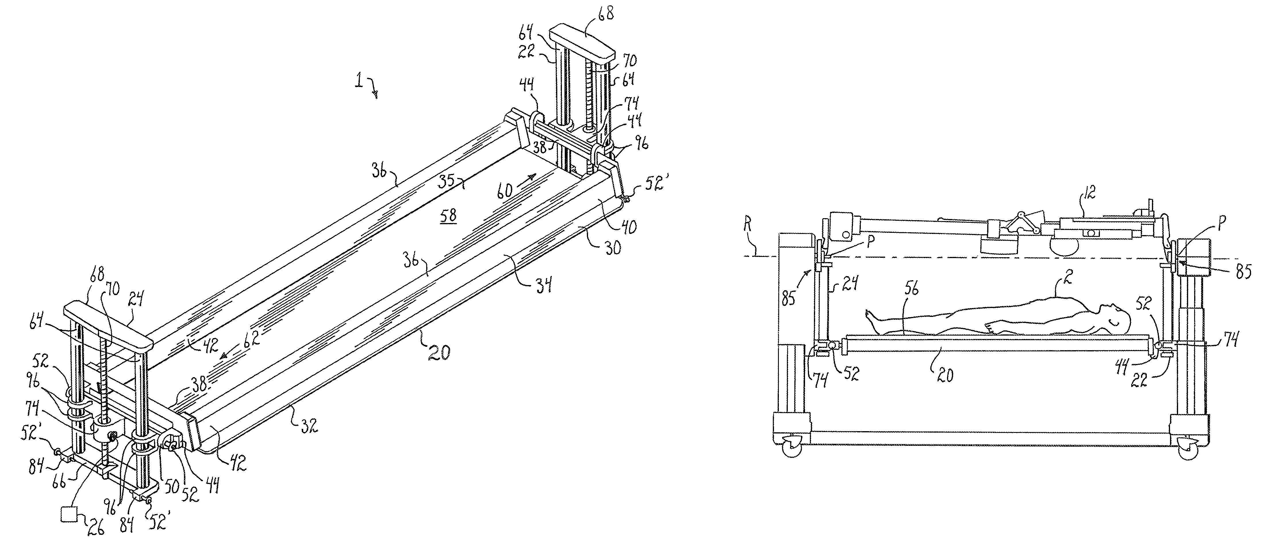
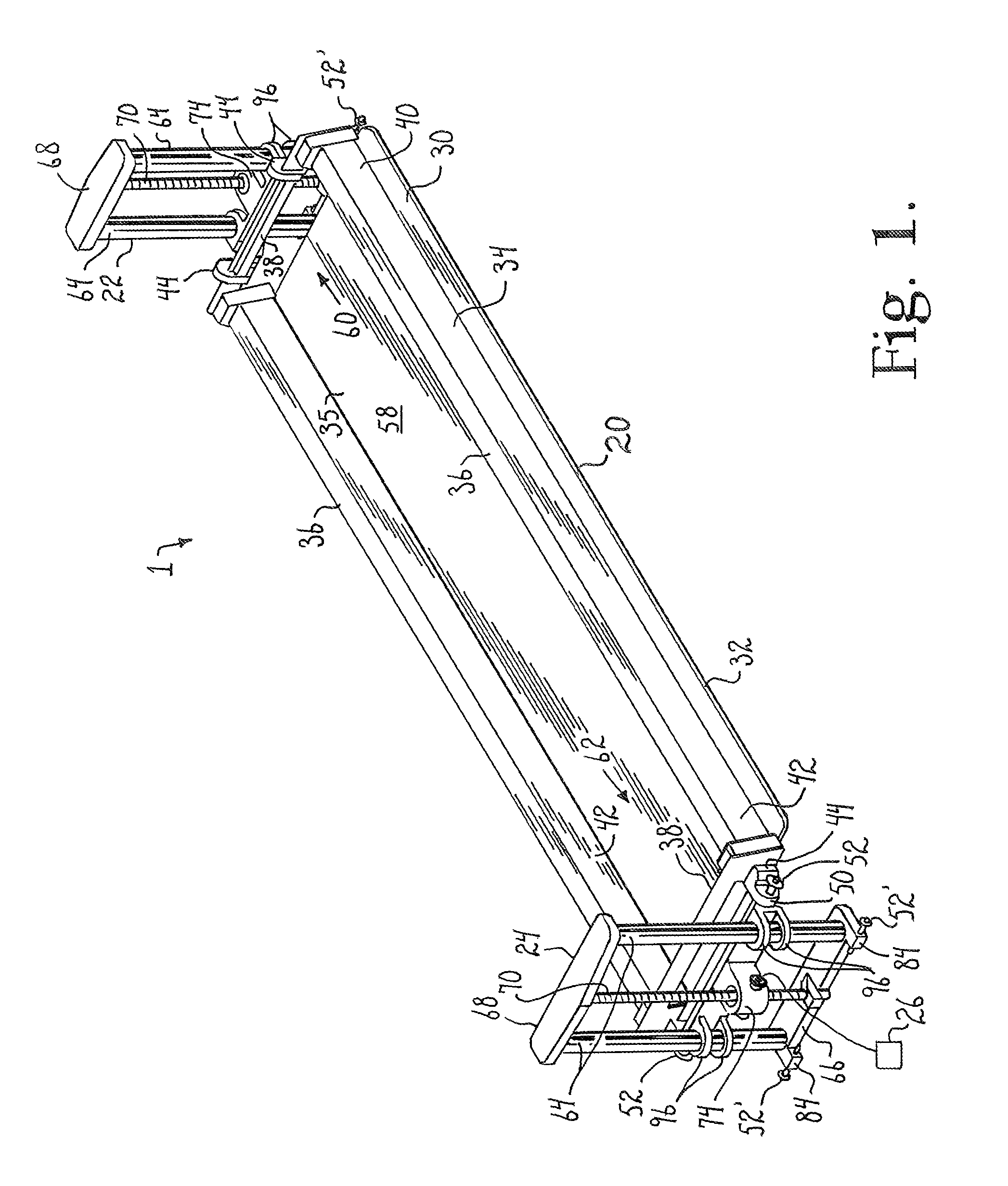
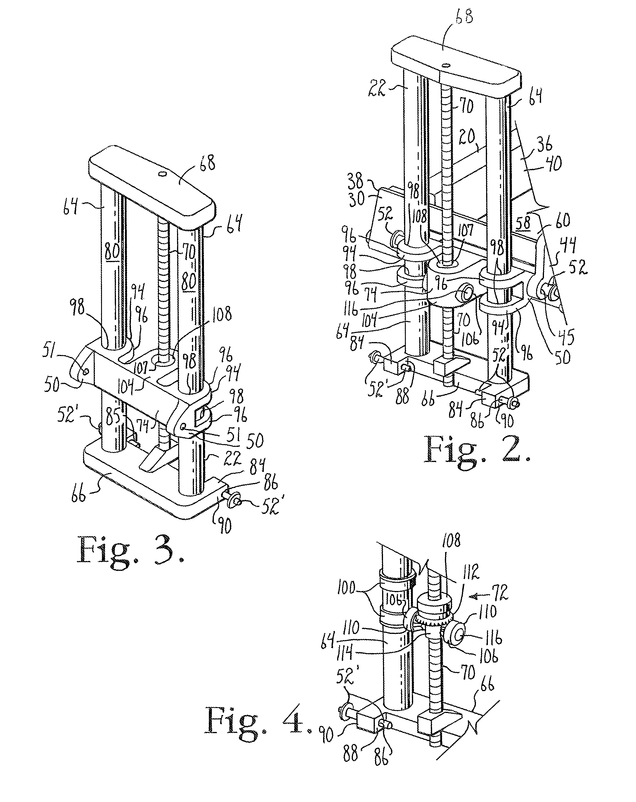
[0037]Referring now to the drawings, a patient elevation and positioning apparatus of the present invention is generally denoted by the numeral 1. The patient elevation and positioning apparatus is useful for positioning a patient 2 in a prone position on a patient positioning support system 4, or surgical table, such as for a medical procedure. An exemplary patient positioning support system 4 is shown in FIGS. 8-13 and is described below.

Patient Pos...


PUM


Abstract

An apparatus for transferring a supine patient to a prone position on a patient positioning support system, and for rotating such a prone patient between prone and supine positions without removing the patient from the patient positioning support system.

Description

CROSS-REFERENCE TO RELATED APPLICATIONS[0001]This application claims the benefit of U.S. Provisional Application No. 61 / 742,167 filed Aug. 3, 2012 and entitled “Synchronized Patient Elevation And Positioning Apparatus For Use With Patient Positioning Support Systems,” the entirety of which is incorporated by reference herein.[0002]This application is also a Continuation-In-Part of U.S. patent application Ser. No. 13 / 317,012, now U.S. Pat. No. 8,719,979, which is a Continuation of U.S. patent application Ser. No. 12 / 460,702, now U.S. Pat. No. 8,060,960, and also which is a Continuation of U.S. patent application Ser. No. 11 / 788,513, now U.S. Pat. No. 7,565,708, the entirety of which are incorporated by reference herein.[0003]U.S. patent application Ser. No. 11 / 788,513 claims the benefit of U.S. Provisional Application No. 60 / 798,288, and is also a Continuation-In-Part of U.S. patent application Ser. No. 11 / 159,494, now U.S. Pat. No. 7,343,635, which is a Continuation-In-Part of U.S. ...

Claims


Application Information

Patent Timeline
Patent Type & Authority Patents(United States)
IPC IPC(8): A61G13/04A61B6/04A61G7/00A61G7/008A61G7/012A61G13/00A61G13/08
CPCA61G13/04A61G13/08A61G2200/327A61G13/0036A61G7/008A61G7/001A61G2210/10A61B6/0407A61G2013/0054A61G7/012A61G2200/325A61G13/0054
Inventor JACKSONGUERRA, LAWRENCE E.HERRON, MICHAEL A.
Owner WARSAW ORTHOPEDIC INC
Learn More