

Suppressor for reducing the muzzle blast and flash of a firearm
- Summary
- Abstract
- Description
- Claims
- Application Information
AI Technical Summary
Benefits of technology
Problems solved by technology
Method used
Image

Examples
Embodiment Construction
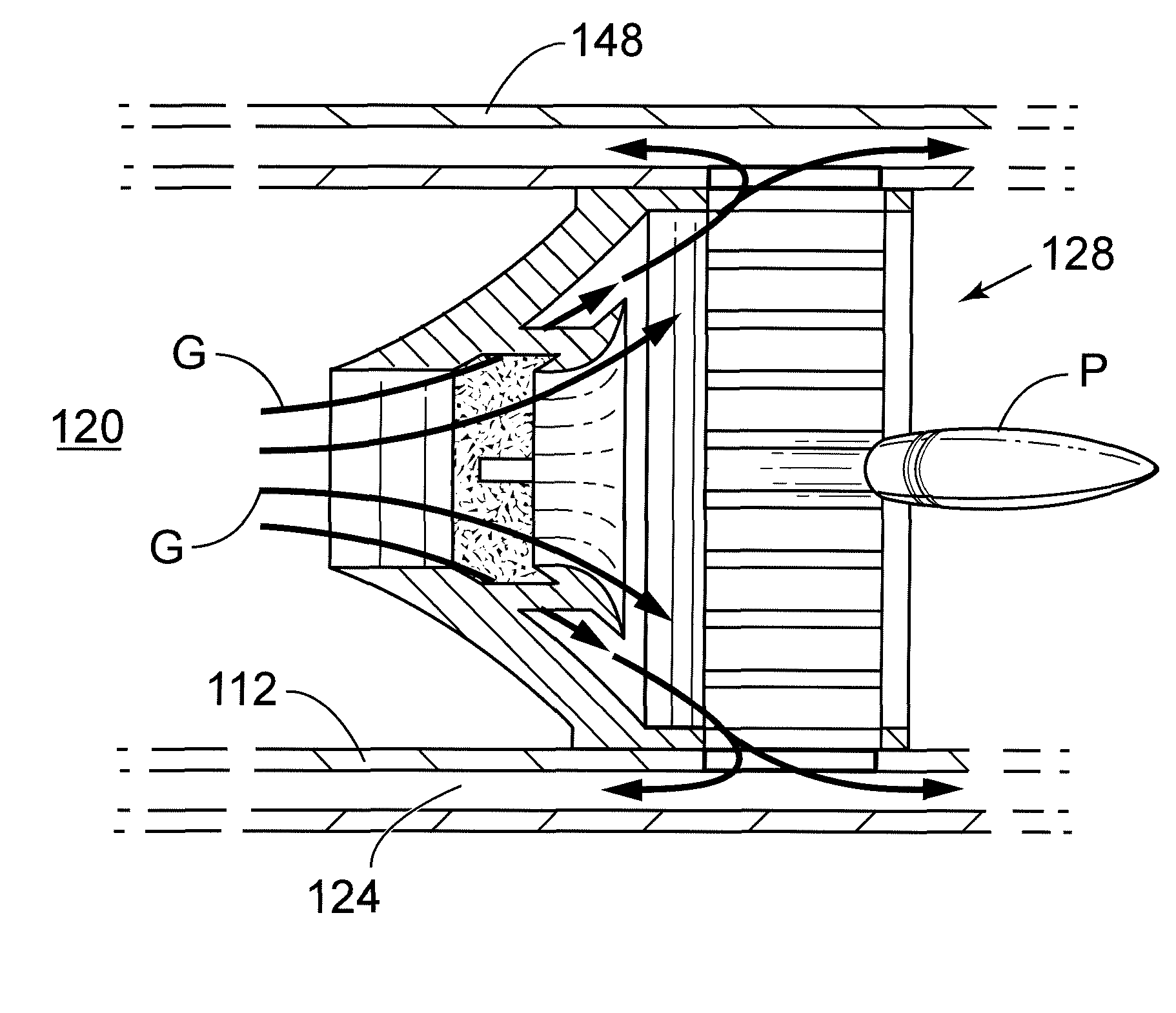
[0044]Suppressors in accordance with examples of the present invention will now be described in greater detail. Computer models of these examples were first generated using a Computer Aided Design (CAD) program before being analyzed with Computational Fluid Dynamics (CFD). The CFD results were examined and each suppressor's geometry was optimized to increase residence time and to reduce the mach number of the gases exiting the suppressor. Please note that various types of firearms are known to have different barrel lengths, use different cartridge loads, and operate at different gas pressures. For this reason, parametric manipulation of some of the claimed elements may be necessary to ensure a suppressor design is optimized for each specific application.
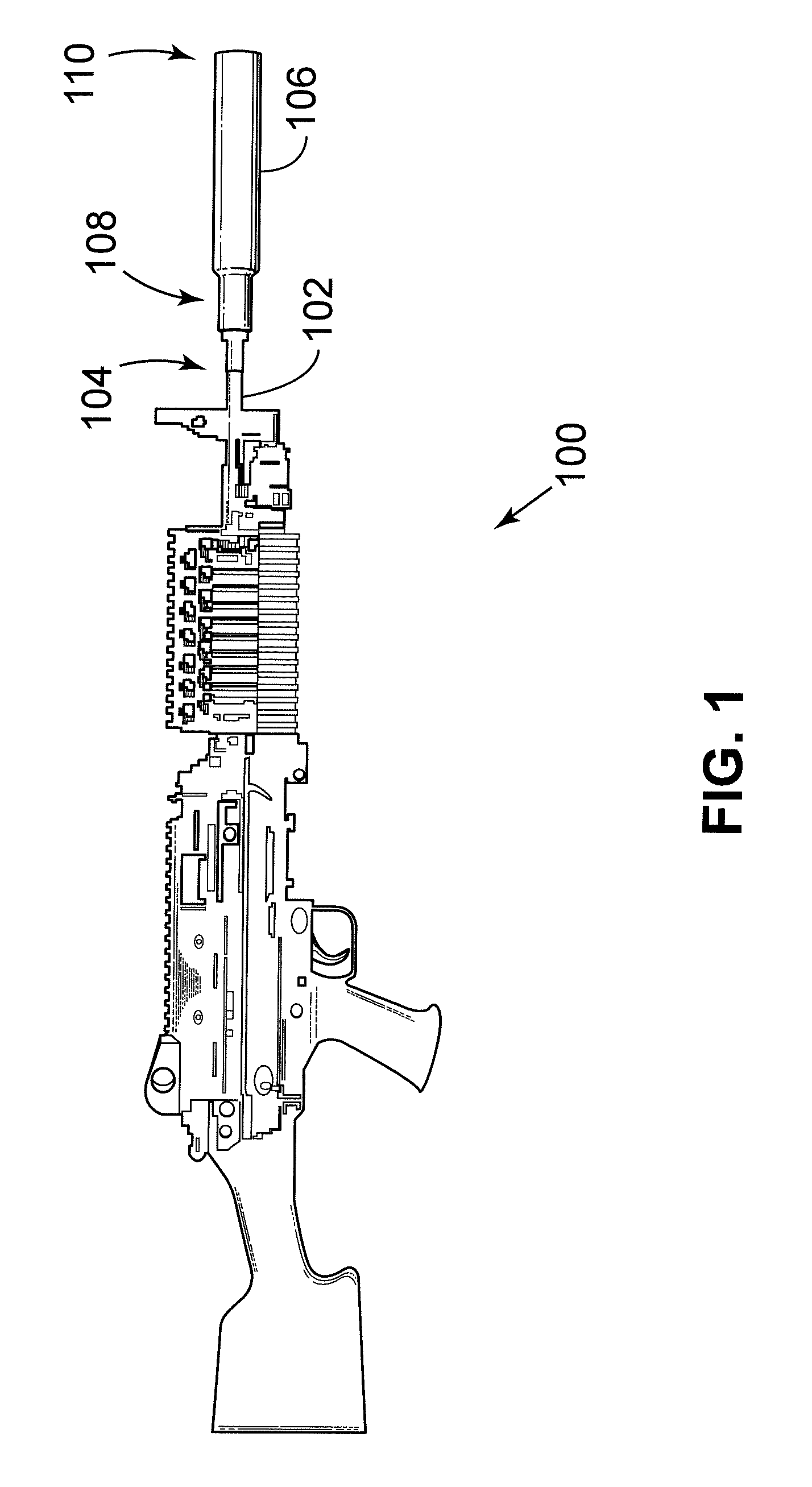
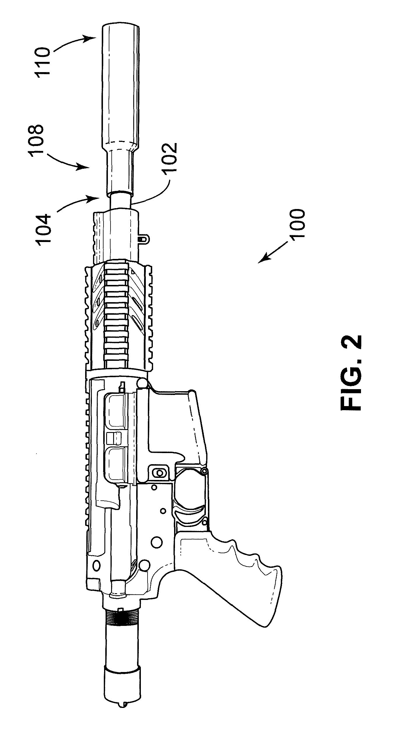
[0045]Referring first to FIGS. 1 and 2, a firearm 100 includes a barrel 102 for discharging a projectile at an intended target. Affixed to a muzzle end 104 of the barrel 102 is a suppressor 106 in accordance with an example of the pr...
PUM
 Abstract
Description
Claims
Application Information