
Vehicle drive control apparatus

a technology of control apparatus and drive shaft, which is applied in the direction of mechanical equipment, machines/engines, transportation and packaging, etc., can solve the problems of providing a sense of discomfort or strangeness to the driver, and achieve the effect of appropriate suppression of a sense of discomfor

Active Publication Date: 2014-10-07
TOYOTA JIDOSHA KK
View PDF6 Cites 0 Cited by
  • Summary
  • Abstract
  • Description
  • Claims
  • Application Information

AI Technical Summary

Benefits of technology

[0008]The invention has been done in view of the circumstances as described above, and an object of the invention is to provide a vehicle drive control apparatus capable of appropriately suppressing the a sense of discomfort given to the driver when the shift position is shifted from the non-driving position to the driving position with the accelerator turned ON.

Problems solved by technology

Under such circumstances, if the drive force is transmitted from the motor to the wheels when the shift position is switched from the non-driving position to the driving position with the accelerator turned ON, this may possibly provide a sense of discomfort or strangeness to the driver.

Method used


Image

  • Vehicle drive control apparatus
  • Vehicle drive control apparatus
  • Vehicle drive control apparatus

Examples


Embodiment Construction

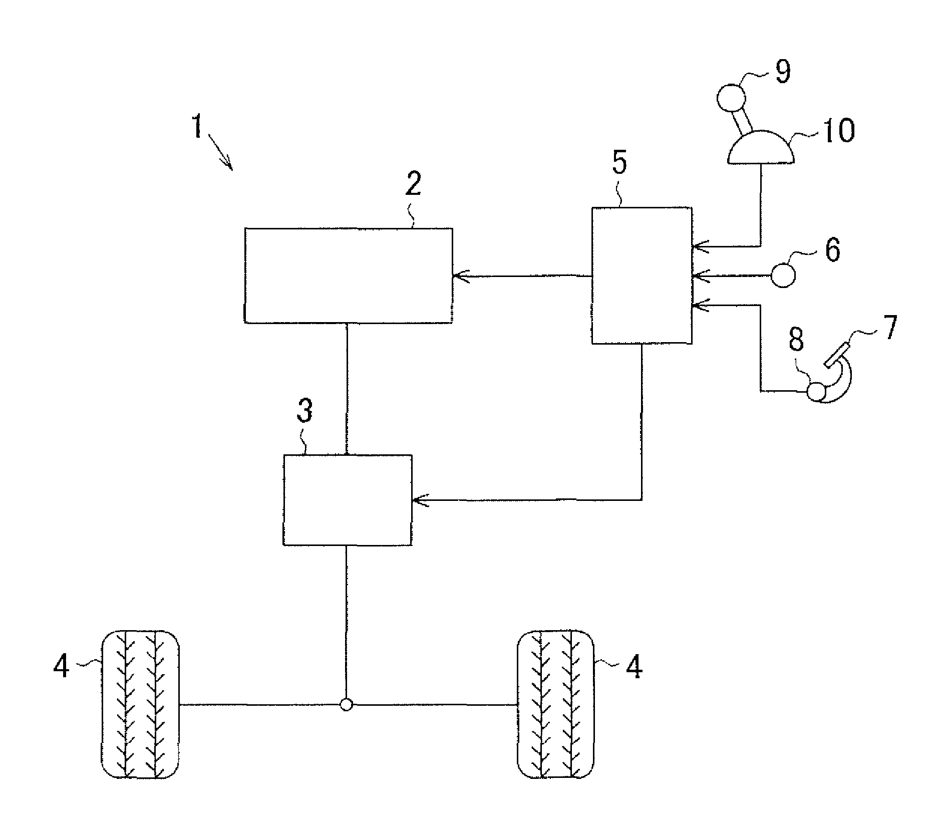
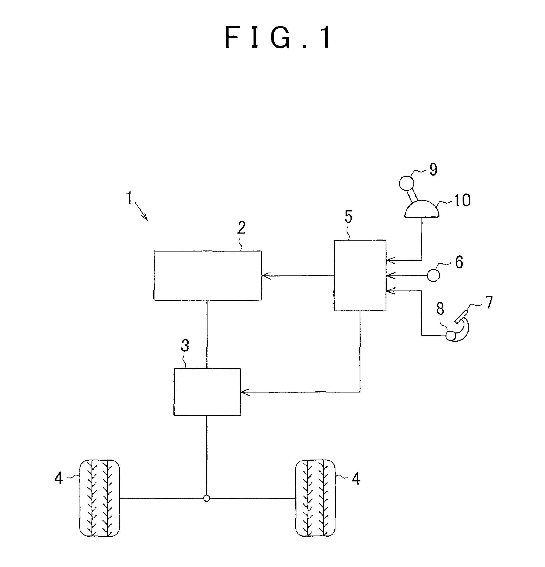
[0034]Referring to FIG. 1 to FIG. 4, an embodiment of a vehicle drive control apparatus according to the invention will be described. As shown in FIG. 1, a vehicle 1 has an internal combustion engine 2 serving as a drive source, and a transmission 3 for transmitting drive force output from the internal combustion engine 2 to wheels 4.

[0035]The vehicle 1 has an internal combustion engine 2 and an electronic controller 5 for performing various types of control in relation to the transmission 3. The electronic controller 5 is composed of a central processing unit (CPU) performing arithmetic processing relating to various types of control, a read-only memory (ROM) storing a program or data for the various type of control, and a random access memory (RAM) temporarily storing a result of the arithmetic processing or the like. The electronic controller 5 reads detection signals from sensors, performs various type of arithmetic processing, and controls the internal combustion engine 2 and t...


PUM


Abstract

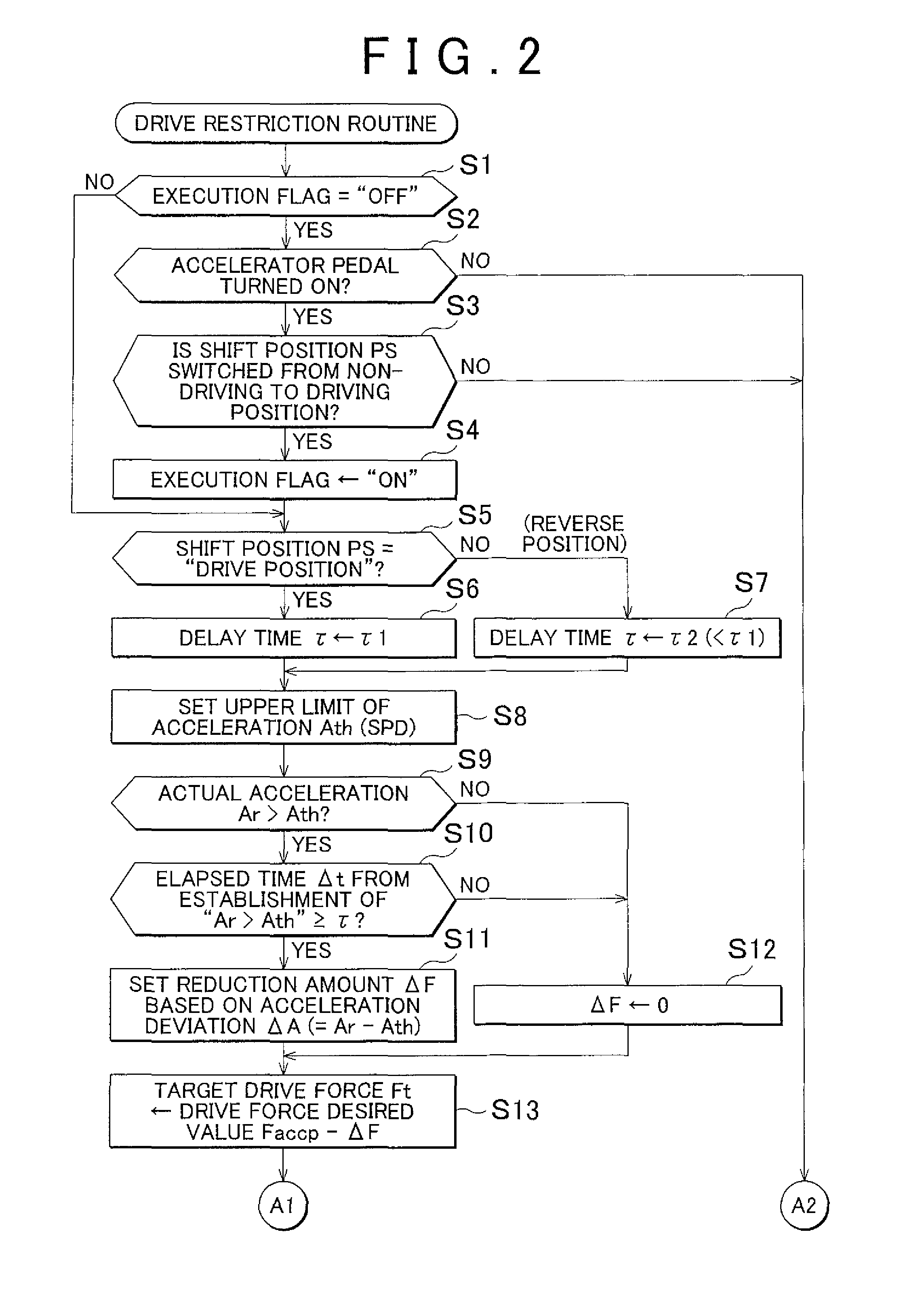
Provided is a vehicle drive control apparatus including a shift mechanism configured to be able to selectively switch its shift position to either a driving position or a non-driving position; and a controller configured to control the drive force output from a motor serving as a drive source of the vehicle according to operation of an accelerator, to transmit the drive force from the motor to wheels when the shift position is in the driving position, and to stop the transmission of the drive force from the motor to the wheels when the shift position is in the non-driving position. The controller also performs drive force suppression processing to control the drive force, when the shift position is switched from the non-driving position to the driving position with the accelerator turned ON, such that the acceleration of the vehicle does not exceed an upper limit of acceleration.

Description

INCORPORATION BY REFERENCE[0001]The disclosure of Japanese Patent Application No. 2011-260566 filed on Nov. 29, 2011 including the specification, drawings and abstract is incorporated herein by reference in its entirety.BACKGROUND OF THE INVENTION[0002]1. Field of the Invention[0003]The invention relates to a vehicle drive control apparatus for controlling drive force output from a motor functioning as a drive source of the vehicle according to operation of an accelerator.[0004]2. Description of the Related Art[0005]As described in Japanese Patent Application Publication No. 61-190135 (JP-61-190135 A), a vehicle such as an automobile has a controller which controls drive force output from a motor according to a driver's operation of an accelerator, and the vehicle is driven by transmitting the drive force output from the motor to wheels. The vehicle further has a shift mechanism which enables the driver to selectively switch the shift position either to a driving position or a non-d...

Claims


Application Information

Patent Timeline
Patent Type & Authority Patents(United States)
IPC IPC(8): B60W10/04B60W10/10F02D29/02F16H59/02F16H59/10F16H59/18F16H63/50
CPCF16H59/02F16H63/50F02D29/02F16H59/10F16H59/18Y10T477/68Y10T74/2014
Inventor KODAMA, SHINYAOHBAYASHI, MOTONARIMINASE, YUKITAKAGI, MASASHITAKAGI, TOSHIHIRO
Owner TOYOTA JIDOSHA KK
Learn More