Engine suspension system

a suspension system and engine technology, applied in the direction of jet propulsion mounting, vehicle components, propulsion parts, etc., can solve the problems of vehicle occupants feeling uncomfortable, etc., to enhance the performance of the engine mount, reduce the uncomfortable feeling of the occupant, and increase the damping coefficient c of the engine mount

Inactive Publication Date: 2016-08-18
TOYOTA JIDOSHA KK
View PDF3 Cites 2 Cited by
  • Summary
  • Abstract
  • Description
  • Claims
  • Application Information

AI Technical Summary

Benefits of technology

[0012]In the meantime, in a region in which the engine speed is low, namely, in a region in which the frequency of engine vibration is low, there is a frequency region (in this example, 7-20 Hz) in which vibration transmitted from a road surface to the vehicle side during traveling of the vehicle resonates with vibration of the engine itself. If the resonance occurs, the vehicle shakes largely, and an occupant of the vehicle feels uncomfortable. In order to suppress the uncomfortable feeling of the occupant caused by the resonance, it is useful to increase the damping coefficient c of the engine mount, and enhance the performance of the engine mount, i.e., its capability of damping vibration transmitted from the road surface to the vehicle.

Problems solved by technology

In the meantime, an occupant of the vehicle may feel uncomfortable when engine vibration is transmitted to the vehicle side.
If the resonance occurs, the vehicle shakes largely, and an occupant of the vehicle feels uncomfortable.
Accordingly, when the engine speed is low, the resonance occurs in the above-indicated frequency region, and the occupant of the vehicle feels uncomfortable.

Method used


Image

  • Engine suspension system
  • Engine suspension system
  • Engine suspension system

Examples


Embodiment Construction

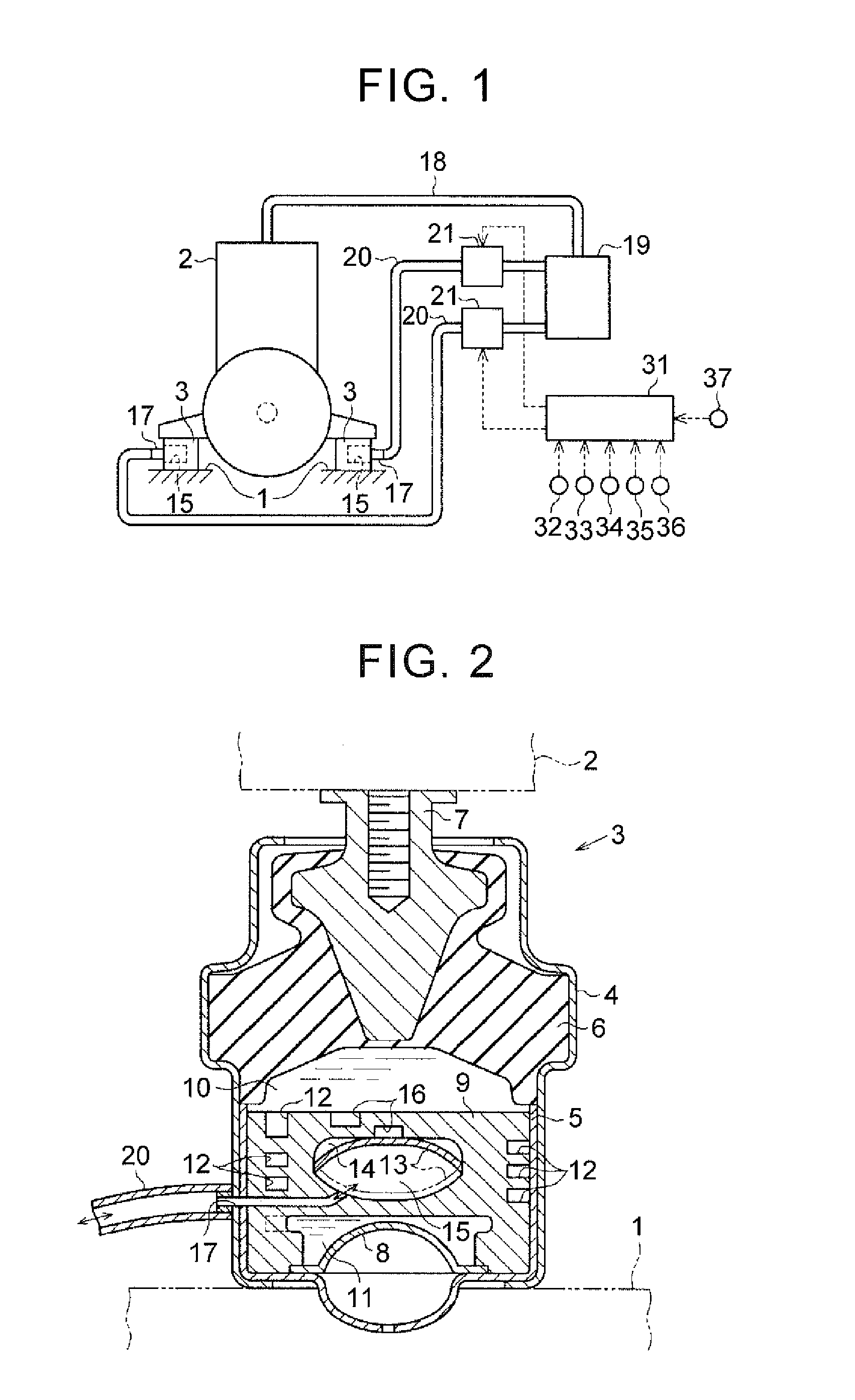
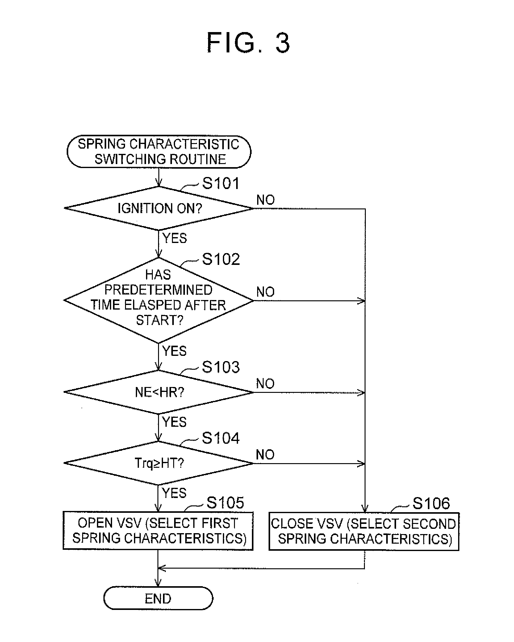
[0028]Referring to FIG. 1 through FIG. 3, a suspension system for an engine in a vehicle according to a first embodiment will be described.

[0029]The suspension system shown in FIG. 1 includes engine mounts 3 that support an engine 2 on a vehicle 1. The engine mounts 3 have the function of curbing transmission of vibration of the engine 2 (which will be called “engine vibration”) to the vehicle 1 side during operation of the engine 2, and damping vibration transmitted from a road surface to the vehicle 1 during traveling of the vehicle 1. The engine mount 3 has a higher capability of curbing transmission of engine vibration to the vehicle 1 side as the spring constant k of the engine mount 3 is smaller. On the other hand, the engine mount 3 has a higher capability of damping vibration transmitted from the road surface to the vehicle as the damping coefficient c of the engine mount 3 is larger.

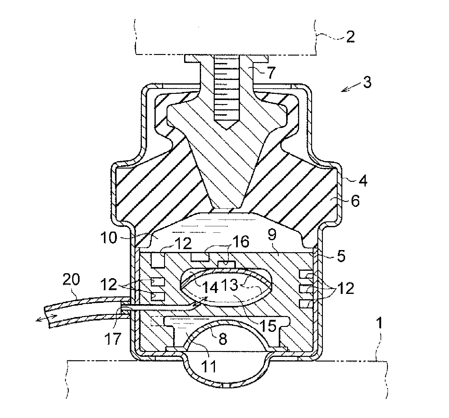
[0030]FIG. 2 is a cross-sectional view showing the internal structure of the engine mount 3....


PUM


Abstract

A suspension system for an engine includes an engine mount and an electronic control unit. The engine mount has spring characteristics that are switchable between first spring characteristics and second spring characteristics. The electronic control unit is configured to switch the spring characteristics of the engine mount to the first spring characteristics when the rotational speed of the engine is lower than a predetermined rotational speed, and torque of the engine is equal to or larger than a predetermined torque. The electronic control unit is configured to switch the spring characteristics of the engine mount to the second spring characteristics when the rotational speed of the engine is lower than the predetermined rotational speed, and the torque of the engine is smaller than the predetermined torque.

Description

INCORPORATION BY REFERENCE[0001]The disclosure of Japanese Patent Application No. 2015-027649 filed on Feb. 16, 2015 including the specification, drawings and abstract is incorporated herein by reference in its entirety.BACKGROUND[0002]1. Technical Field[0003]The disclosure relates to a suspension system for an engine.[0004]2. Description of Related Art[0005]A suspension system for an engine in a vehicle includes an engine mount that supports the engine on the vehicle. The engine mount has the function of curbing transmission of engine vibration to the vehicle side, and damping vibration transmitted from a road surface to the vehicle. In the engine mount, the capability of curbing transmission of engine vibration to the vehicle side is enhanced as the spring constant of the engine mount is smaller. On the other hand, in the engine mount, the capability of damping vibration transmitted from the road surface to the vehicle is enhanced as the damping coefficient of the engine mount is ...

Claims


Application Information

Patent Timeline
Patent Type & Authority Applications(United States)
IPC IPC(8): B60K5/12
CPCB60K5/1208B60K5/1283
Inventor SUGITA, YUSUKEMURATA, HIDEKIYOSHIDA, NOBUYAMIYA, HIROSHI
Owner TOYOTA JIDOSHA KK
Why Eureka
Try Eureka