
Control device for continuously variable transmission of vehicle

a technology of control device and transmission device, which is applied in fluid gearings, transportation and packaging, and gearings, etc., can solve the problems of unstable transmission input rotational speed and driver discomfort, and achieve the effect of suppressing driver discomfort and preventing driver discomfor

Active Publication Date: 2019-01-22
JATCO LTD
View PDF7 Cites 0 Cited by
  • Summary
  • Abstract
  • Description
  • Claims
  • Application Information

AI Technical Summary

Benefits of technology

[0005]The present invention is made with attention to the problem described above, and is targeted for providing a vehicular continuously variable transmission control device that provides a driver with a direct step shift feel by simulated step shifting while suppressing the driver from feeling uncomfortable.
[0007]Accordingly, when the sensed value of the oil temperature is higher than the first oil temperature threshold value while the vehicle is running, engagement of the lockup clutch is permitted. When the sensed value of the oil temperature is lower than or equal to the second oil temperature threshold value, wherein the second oil temperature threshold value is set higher than or equal to the first oil temperature threshold value, the simulated step shift mode is inhibited from being employed for shifting. When the sensed value of the oil temperature is higher than the second oil temperature threshold value, the simulated step shift mode is permitted to be employed for shifting. Namely, when the vehicle is running under the oil temperature condition where the lockup clutch is disengaged, the simulated step shift mode is inhibited from being employed for shifting. This serves to suppress a driver from feeling uncomfortable due to lack of stability of the transmission input rotational speed as in the case where the simulated step shift mode is permitted for shifting at low oil temperature. Then, when the vehicle is running under the oil temperature condition where the lockup clutch is engaged, the simulated step shift mode is permitted to be employed for shifting. This serves to provide simulated step shifting with direct connection between the drive source and the continuously variable transmission mechanism, and cause the transmission input rotational speed to follow a stepwise change of the transmission ratio, and thereby provide the driver with a direct step shift feel. This results in providing the driver with the direct step shift feel by simulated step shifting while suppressing the driver from feeling uncomfortable.

Problems solved by technology

However, if the simulated step shift mode is performed at low oil temperature in the conventional vehicular continuously variable transmission control device, the transmission input rotational speed becomes unstable, for example, because an engine rotational speed does not fall but remains high even when an upshift is performed.
This causes a problem that a driver may feel uncomfortable when the simulated step shift mode is employed for shifting at low oil temperature.

Method used


Image

  • Control device for continuously variable transmission of vehicle
  • Control device for continuously variable transmission of vehicle
  • Control device for continuously variable transmission of vehicle

Examples


first embodiment

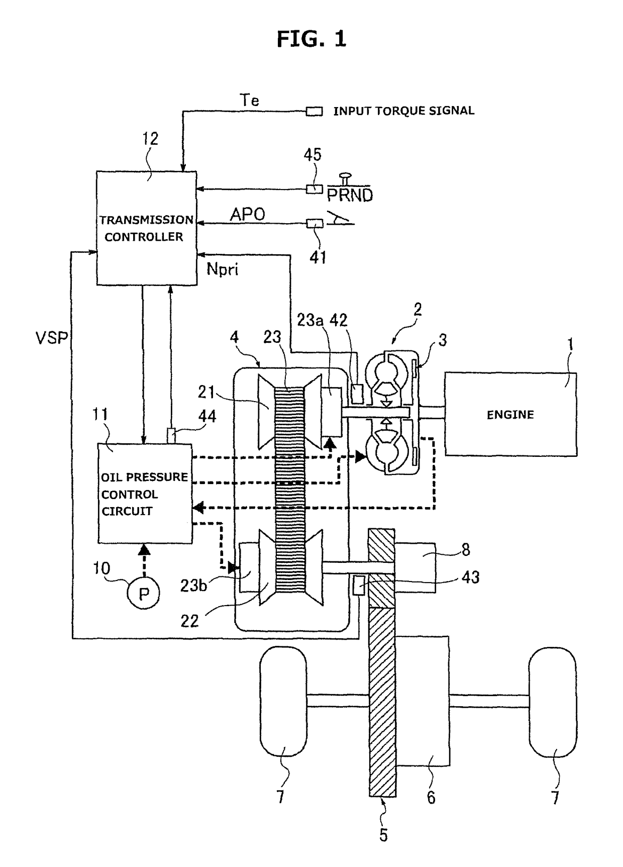
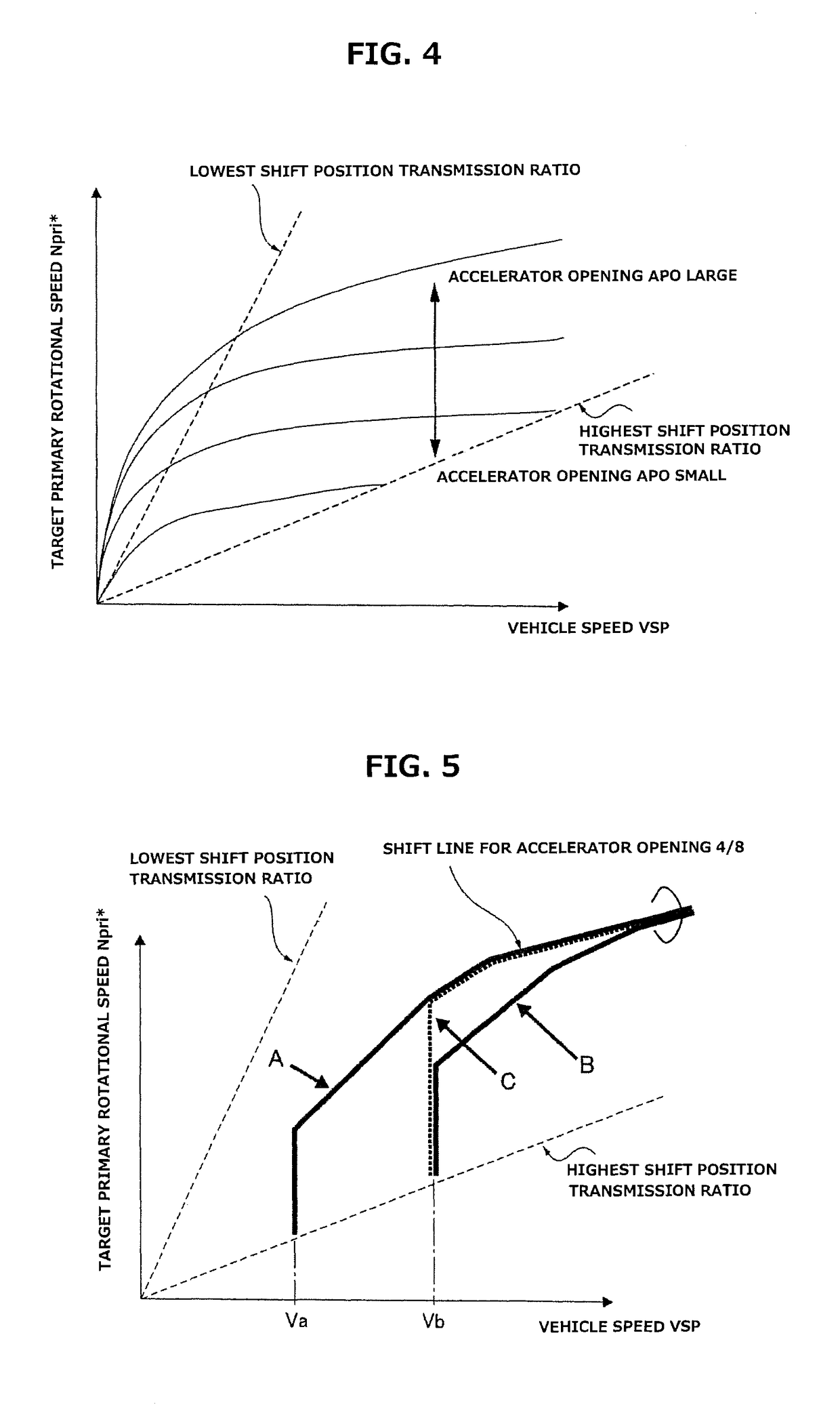
[0018]First, the following describes configuration. The control device according to the first embodiment is applied to an engine vehicle where a torque converter with a lockup clutch and a belt-type continuously variable transmission are mounted in a drive line. The following describes configuration of the vehicular continuously variable transmission control device according to the first embodiment in separate sections [Whole System Configuration], [Lockup Control Configuration], [Shift Control Configuration in Continuous Shift Mode], [Shift Control Configuration in Linear Shift Mode], [Shift Control Configuration in DSTEP Shift Mode], and [Shift Mode Switching Control Process Configuration].

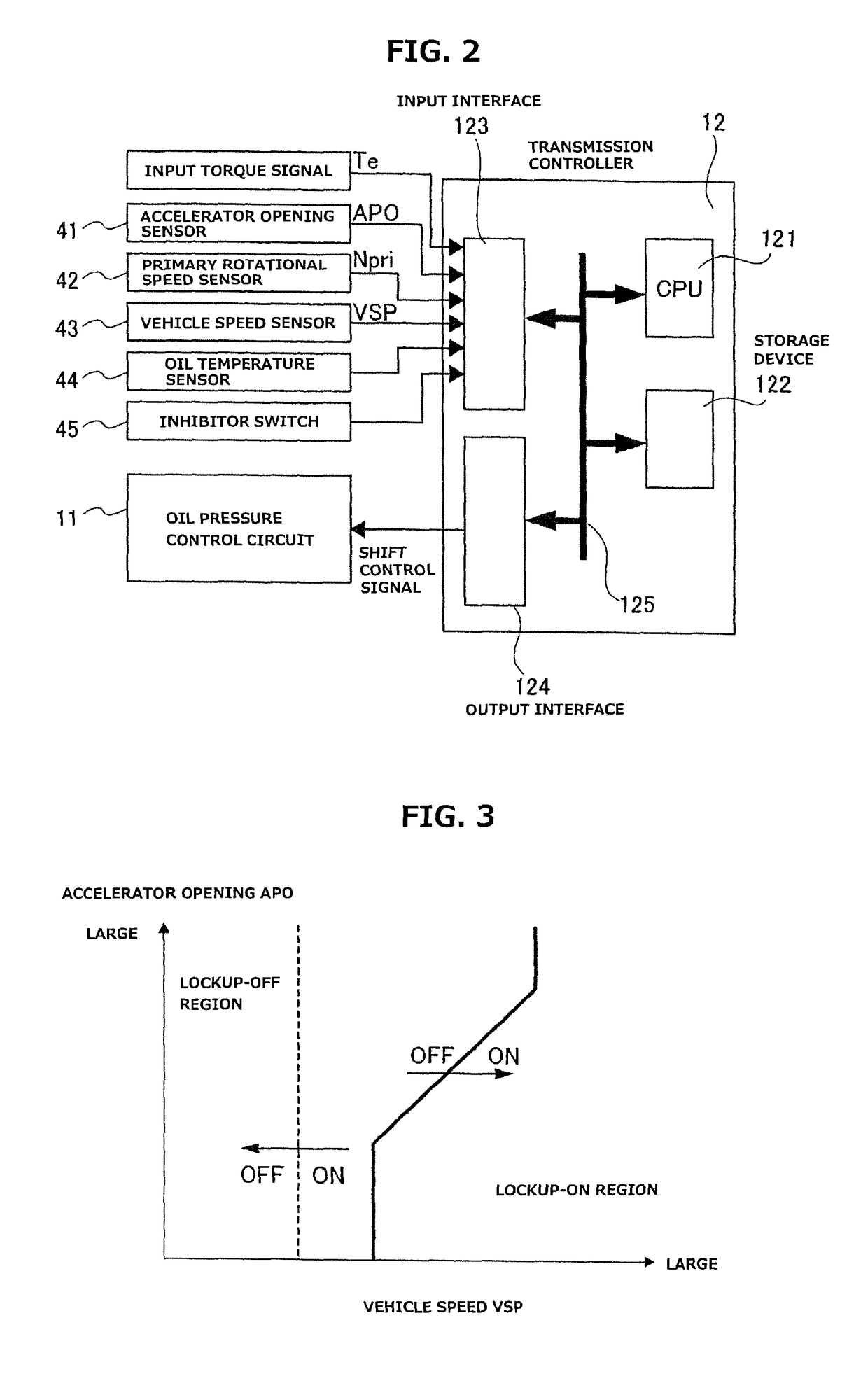
[0019][Whole System Configuration]FIG. 1 shows schematic configuration of an engine vehicle where a vehicular continuously variable transmission, to which a control device according to a first embodiment is applied, is mounted. FIG. 2 shows internal configuration of a transmission controller. Th...


PUM


Abstract

The drive system from the engine (1) to the drive wheels (7) of a vehicle is equipped with a torque converter (2), which has a lock-up clutch (3), and a variator (4). Said engined car is provided with a lock-up control means for controlling the engagement / disengagement of the lock-up clutch (3) and a gear change mode switch-controlling means (FIG. 8) for performing control to switch between a “continuously variable gear change mode” and a “DSTEP gear change mode.” While traveling, the gear change mode switch-controlling means (FIG. 8) prohibits gear change by the “DSTEP gear change mode” when the detected oil temperature is at or below a lock-up engagement-permitting threshold for permitting engagement of the lock-up clutch (3) and allows gear change by the “DSTEP gear change mode” when the detected oil temperature is higher than the lock-up engagement-permitting threshold.

Description

TECHNICAL FIELD[0001]The present invention relates to a control device for a continuously variable transmission for a vehicle where a torque converter and a continuously variable transmission mechanism are mounted in a driveline from a drive source to a driving wheel, wherein the torque converter includes a lockup clutch.BACKGROUND ART[0002]Conventionally known is a control device in a continuously variable transmission for a vehicle including a torque converter, wherein the control device employs a simulated step shift mode, wherein the simulated step shift mode is configured to set a target input rotational speed so as to repeat gradual increase and rapid decrease of a transmission input rotational speed during acceleration of the vehicle, and thereby vary a transmission ratio in a stepwise manner (see a patent document 1, for example).[0003]However, if the simulated step shift mode is performed at low oil temperature in the conventional vehicular continuously variable transmissio...

Claims


Application Information

Patent Timeline
Patent Type & Authority Patents(United States)
IPC IPC(8): B60W10/107B60W30/182F16H61/14F16H61/02F16H61/66B60W10/02B60W30/18F16H59/72
CPCB60W30/182B60W10/107B60W30/18109F16H61/0213F16H61/14F16H61/66B60W10/026F16H2061/6615B60W2510/107B60W2520/10B60W2520/105B60W2540/10B60W2710/024B60W2710/1005F16H59/72F16H2061/6611F16H61/0265F16H61/143
Inventor HONMA, TOMOAKITANABE, AKIHIROSASAKI, TOMOKO
Owner JATCO LTD
Learn More