
High volume multiple component projectile assembly

a projectile and high-volume technology, applied in the field of ammunition, can solve problems such as reducing the effectiveness of projectiles

Active Publication Date: 2014-10-14
LIBERTY OPCO LLC
View PDF22 Cites 210 Cited by
  • Summary
  • Abstract
  • Description
  • Claims
  • Application Information

AI Technical Summary

Benefits of technology

The patent text describes a new invention that eliminates the randomness of depressions in projectiles caused by firearms. The technical effect of this invention is improved accuracy and consistency in the formation of depressions, which can enhance the performance and reliability of firearms.

Problems solved by technology

However, the rifling in a gun barrel causes compression of the interface and the number of such compressions, as well as the location, depth and longitudinal extent of the compression is essentially uncontrollable, thereby reducing the effectiveness of the projectile.

Method used


Image

  • High volume multiple component projectile assembly
  • High volume multiple component projectile assembly
  • High volume multiple component projectile assembly

Examples


first embodiment

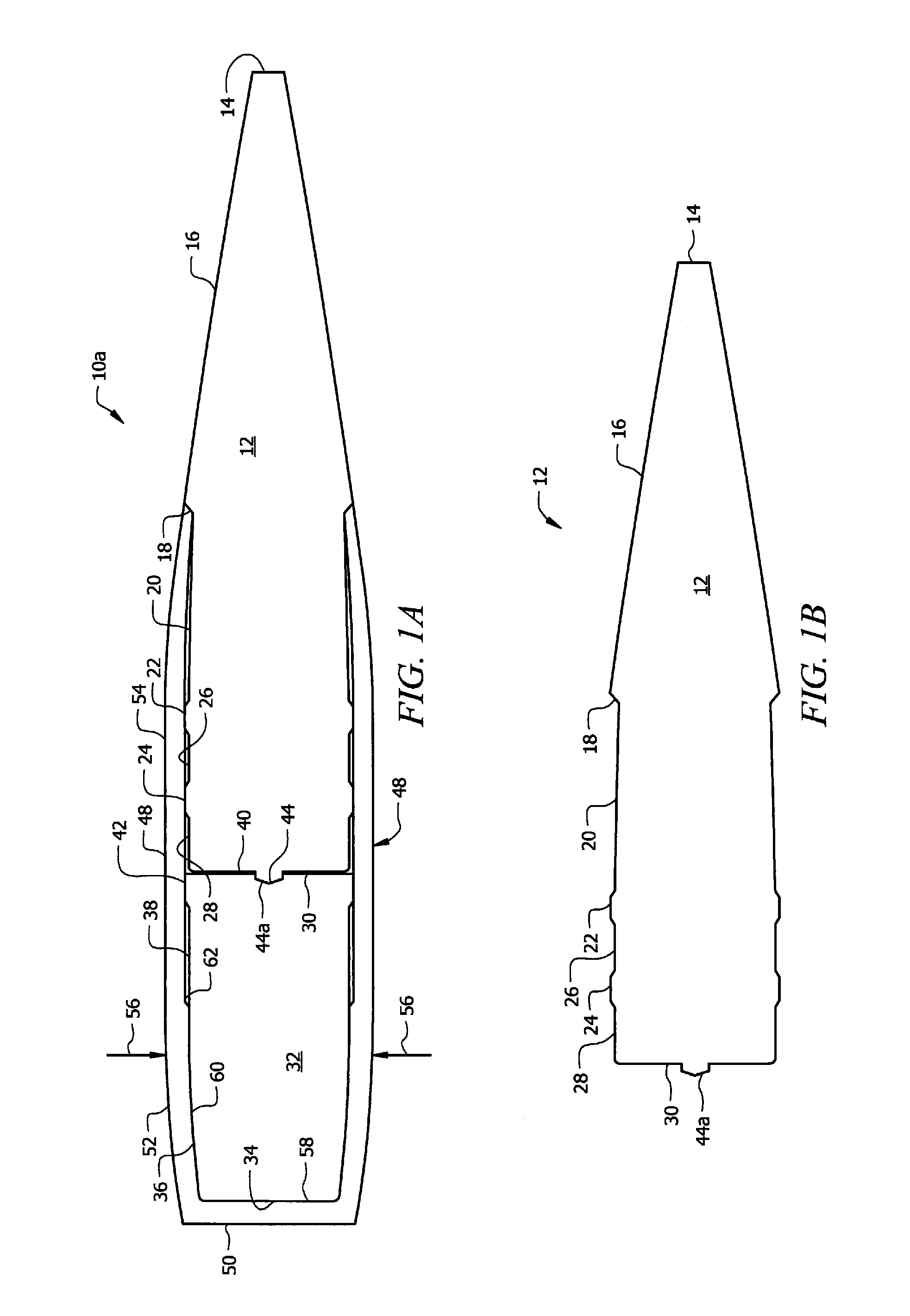
[0043]the novel structure is denoted as a whole in FIG. 1A by the reference numeral 10a.

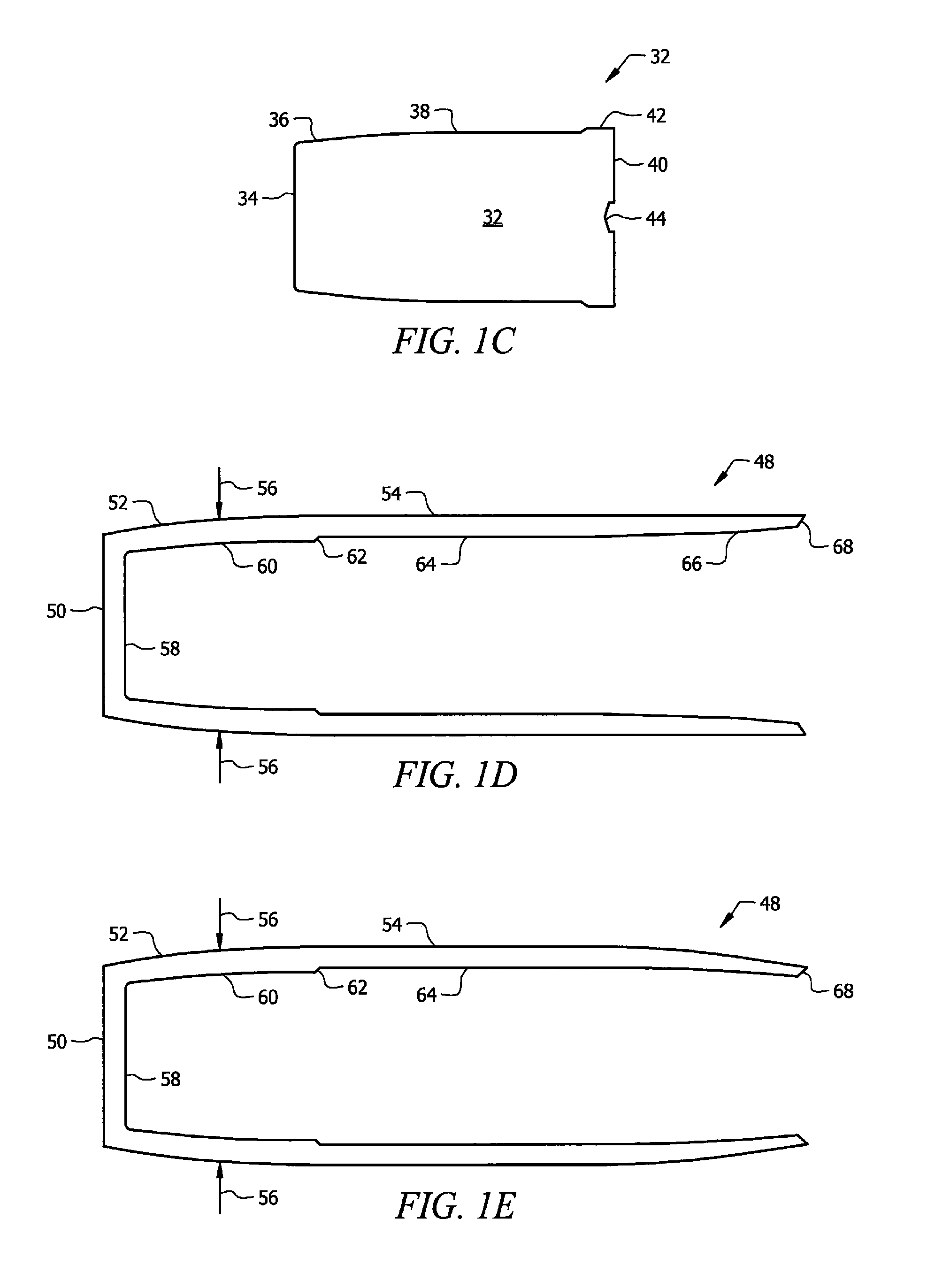
[0044]Structure 10a includes head 12, tail 32, and interface 48. Head 12 is depicted individually in FIG. 1B, tail 32 is depicted individually in FIG. 1C, and interface 48 is depicted individually in FIGS. 1D and 1E.

[0045]Leading end 14 of head 12 can be flat as depicted, rounded, or pointed. Frusto-conical section 16 extends from leading end 14 to a point about mid-length the length of said head. Diameter-reducing annular step 18 is formed at said location and the diameter of head 12 is reduced from said step 18 to the trailing end of said head. The reduced diameter increases slightly but linearly as at 20 from said annular step 18 to first transversely disposed annular ridge 22. The diameter of head 12 is uniform from first ridge 22 to second transversely disposed annular ridge 24 and is again uniform until it reaches flat trailing wall 30.

[0046]The leading end of interface 48 abuts diameter-r...

second embodiment

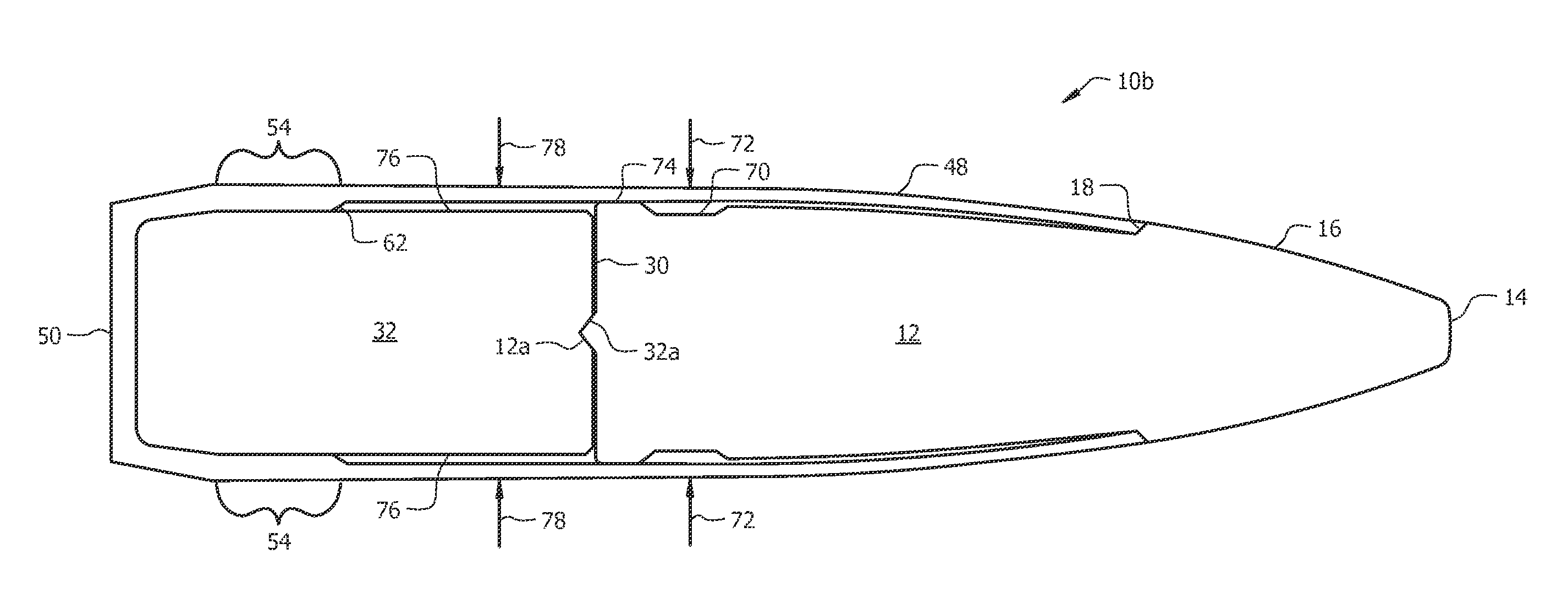
[0066]In this second embodiment, interface 48 is pre-compressed radially inwardly into annular recess 70 during assembly as indicated by directional arrows 72. The compression is produced by a cannelure die that also produces a bullet knurl with symmetrically arranged pronged teeth. A wheel die would deform the bullet shape.

[0067]In this second embodiment, annular diameter-reducing step 18 is formed in head 12 about one-third of the way from its flat leading end 14 to its flat trailing end 30. As in the first embodiment, the leading end of interface 48 has a thickness equal to the depth of step 18 so that an exterior surface of head 12 is flush with an exterior surface of interface 48.

[0068]The internal diameter of interface 48 in this second embodiment increases at diameter increasing step 62 so that annular recess 76 is created between said interface and tail 32. Annular recess 76 facilitates projectile assembly by reducing misalignment during such assembly. After assembly, radial...

third embodiment

[0075]Head 12 of this third embodiment is individually depicted in FIG. 3B and tail 32 is individually depicted in FIG. 3C.


PUM


Abstract

A projectile includes a head, a tail, and an interface that interconnects the head and tail. Multiple sections of the interface are deformed by being compressed radially inwardly into respective annular recesses formed between the interface and the head and tail during manufacturing or by rifling when the projectile is fired. The amount of deformation is controlled by the depth of each of the annular recesses. In all embodiments, annular ridges formed in the head, the tail, or both, define the longitudinal extent of the annular recesses. The interface includes an annular obturation region and has a beveled open leading end to facilitate insertion of the head and tail into the interface.

Description

BACKGROUND OF THE INVENTION[0001]1. Field of the Invention[0002]This invention relates to ammunition. More specifically, it relates to a projectile that is advantageously deformed by rifling.[0003]2. Brief Description of the Related Art[0004]Projectiles that include a head and a tail held together by an interface have enhanced performance characteristics relative to conventional projectiles.[0005]However, the rifling in a gun barrel causes compression of the interface and the number of such compressions, as well as the location, depth and longitudinal extent of the compression is essentially uncontrollable, thereby reducing the effectiveness of the projectile. Accordingly, multiple projectiles fired in sequence will follow differing paths of travel due to the random quantity, location, depth and extent of the compressions formed in the interface.[0006]The conventional wisdom is that such compression is a natural consequence of rifling and that nothing can be done about it.[0007]In v...

Claims


Application Information

Patent Timeline
Patent Type & Authority Patents(United States)
IPC IPC(8): F42B30/02
CPCF42B33/001F42B30/02F42B14/00F42B14/02F42B12/78F42B12/02F42B12/367
Inventor MARX, P, J
Owner LIBERTY OPCO LLC
Learn More