
Filter system

a filter system and filter body technology, applied in the direction of filtration separation, hollow article cleaning, separation process, etc., can solve the problems of unsanitary methods, ineffectiveness, harmful to patients, etc., to promote a more efficient and even accumulation of cut hairs, increase the longevity and effectiveness of filter members, and ensure the effect of cleaning

Active Publication Date: 2014-11-04
SURGICAL SITE SOLUTIONS
View PDF14 Cites 0 Cited by
  • Summary
  • Abstract
  • Description
  • Claims
  • Application Information

AI Technical Summary

Benefits of technology

The invention is a filter assembly that attaches to a vacuum and works with a hair clipper. It has a housing with a top and bottom, and a filter member. The assembly is designed to collect hair efficiently and allow air to pass through. The unique configuration creates a vortex and increases the longevity of the filter. The filter is easy to remove and dispose of, reducing mess and potential contamination.

Problems solved by technology

This method is unsanitary, inefficient and misses many hair clippings, all of which are potentially harmful to the patient.
Furthermore, adhesive tapes are not typically kept under sterile conditions.
This increases the risk of spreading infectious contaminants through the surgical suite and possibly throughout the medical facility.
In addition, patients may be allergic or otherwise reactive to the adhesive used in tape.
Clippers having a vacuum capability have been used with some success, but these often exacerbate the situation when, for example, vacuum filtration is inadequate, unsanitary, or requires frequent cleaning.
This practice is cumbersome and unsanitary.

Method used


Image

  • Filter system
  • Filter system
  • Filter system

Examples


Embodiment Construction

[0019]Although the disclosure hereof is detailed and exact to enable those skilled in the art to practice the invention, the physical embodiments herein disclosed merely exemplify the invention which may be embodied in other specific structures. While the preferred embodiment has been described, the details may be changed without departing from the invention, which is defined by the claims.

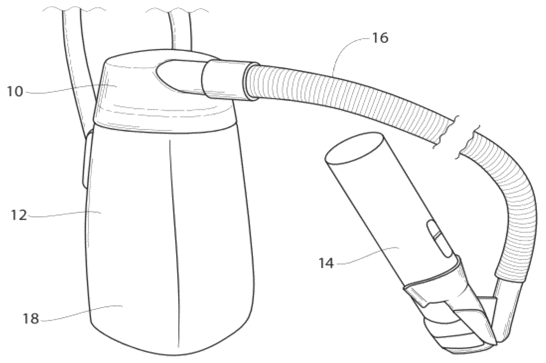
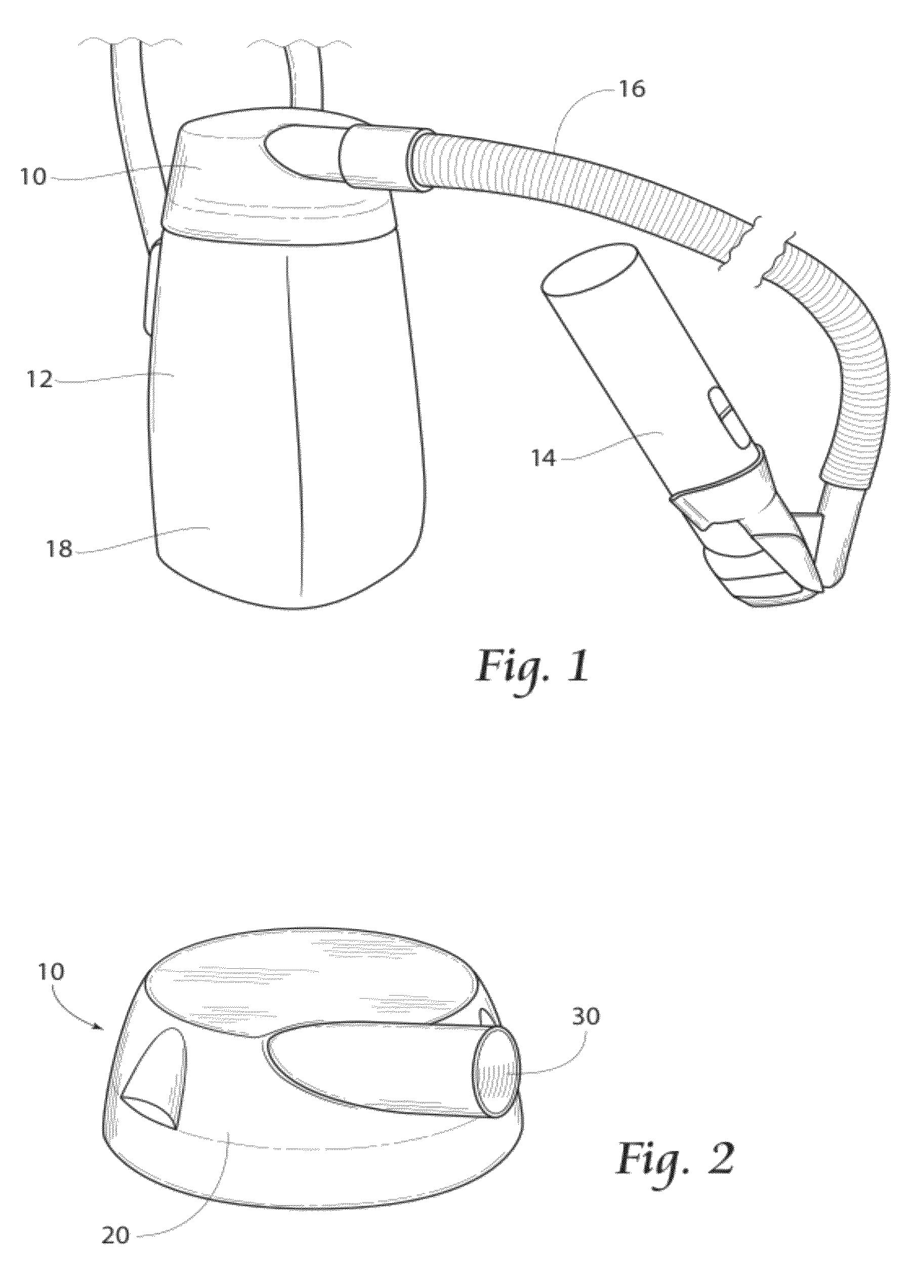
[0020]As seen in the view of FIG. 1, the present invention pertains to a filter assembly 10 that is designed to securely attach to a vacuum apparatus 12 and for use in conjunction with a hair clipper 14. As illustrated, a clipper 14 may be used to initially remove hair from a target site, such as a surgical area. A vacuum apparatus 12, such as the one depicted in FIG. 1, draws the cut hair through a vacuum hose 16 and into a canister 18.

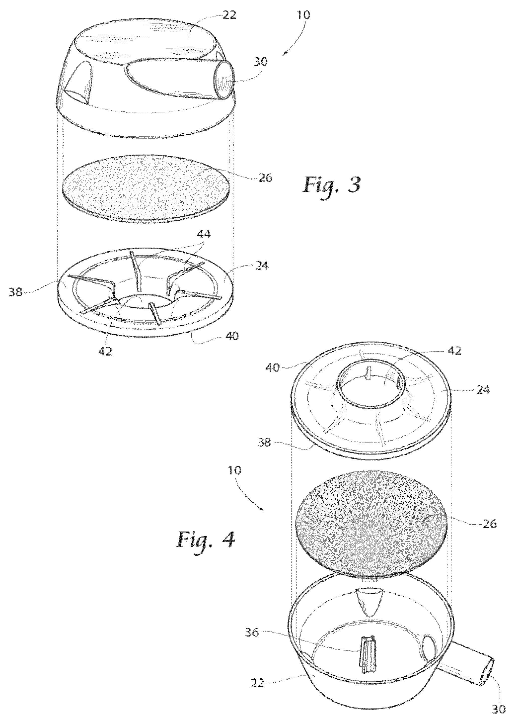
[0021]As illustrated in FIGS. 2-4, an assembly 10 according to the present invention preferably includes a housing 20 having a top piece 22 and a bottom piece 24. ...


PUM

PropertyMeasurementUnit
perimeteraaaaaaaaaa
circular perimeteraaaaaaaaaa
vacuumaaaaaaaaaa

Abstract

A method of collecting cut hair is disclosed. The steps include providing a vacuum source and a filter assembly having a top piece, a bottom piece, and a filter member. The assembly has a generally circular perimeter. A vacuum is applied to the assembly interior, and the cut hairs are moved through the aperture and into the assembly. The cut hairs are circulated in a collecting vortex and collected on the filter member.

Description

FIELD OF THE INVENTION[0001]The present invention relates to a hair clipper filtering assembly and a method for clipping, removing shaved or clipped hair from the clipped site, and filtering the clipped hair. More specifically, the present invention is a disposable hair clipper filter assembly.BACKGROUND OF THE INVENTION[0002]Clipping of hair is a common action and is often performed on sites which further require removal of the clipped hair. An example of such a site may be found in the surgical arena, in which the areas of incision on surgical patients may be shaved prior to invasive or surgical procedures to thereby remove hair that might harbor germs and thus serve as a source of contamination. Loose hair clippings that remain on the patient fall onto the sheets, covers and bed surroundings and must be picked up and removed. At present, the most common protocol for picking up the loose hair clippings is to press an adhesive backed material, usually tape, against the area where t...

Claims


Application Information

Patent Timeline
Patent Type & Authority Patents(United States)
IPC IPC(8): B08B5/04
CPCB26B19/44B01D46/0002B01D46/0046
Inventor PANZER, LARRY, H.
Owner SURGICAL SITE SOLUTIONS
Learn More