Supercharge Your Innovation With Domain-Expert AI Agents!

Adjustable steering column lock

a technology of steering column lock and adjustable position, which is applied in the direction of steering parts, alternative steering control, vehicle components, etc., can solve the problems of limited adjustment of the steering column in the telescope direction, complex design and associated costs, and finite number of adjustment positions available in the rake and telescope directions

Inactive Publication Date: 2014-11-11
STEERING SOLUTIONS IP HLDG
View PDF11 Cites 10 Cited by
  • Summary
  • Abstract
  • Description
  • Claims
  • Application Information

AI Technical Summary

Problems solved by technology

In the locked position, the telescope lock teeth and the telescope slot teeth are engaged such that adjustment of the steering column in the telescope direction is limited.
One drawback to the arrangement above is that when the locking lever is rotated from an unlocked position to a locked position, peak areas of the lock teeth on the rake body and / or telescope body may come into contact with peak areas of the lock teeth within the respective rake and / or telescope slot.
Further, there are only a finite number of adjustment positions available in the rake and telescope directions, limited by the number of corresponding lock teeth between the rake body and telescope body and the respective slots.
Drawbacks to the friction plate configuration include complexity of design and the associated costs.

Method used


Image

  • Adjustable steering column lock
  • Adjustable steering column lock
  • Adjustable steering column lock

Examples


Embodiment Construction

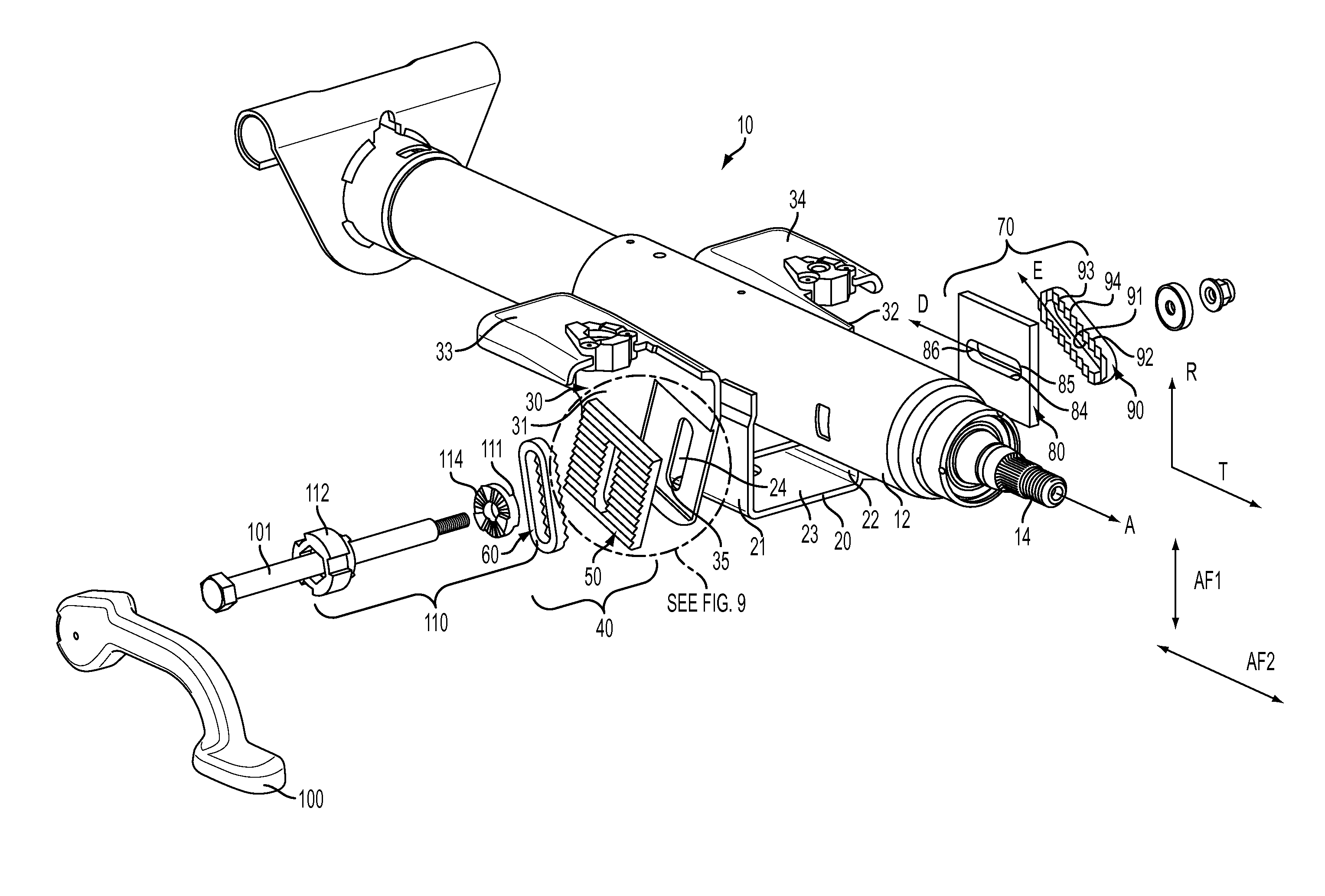
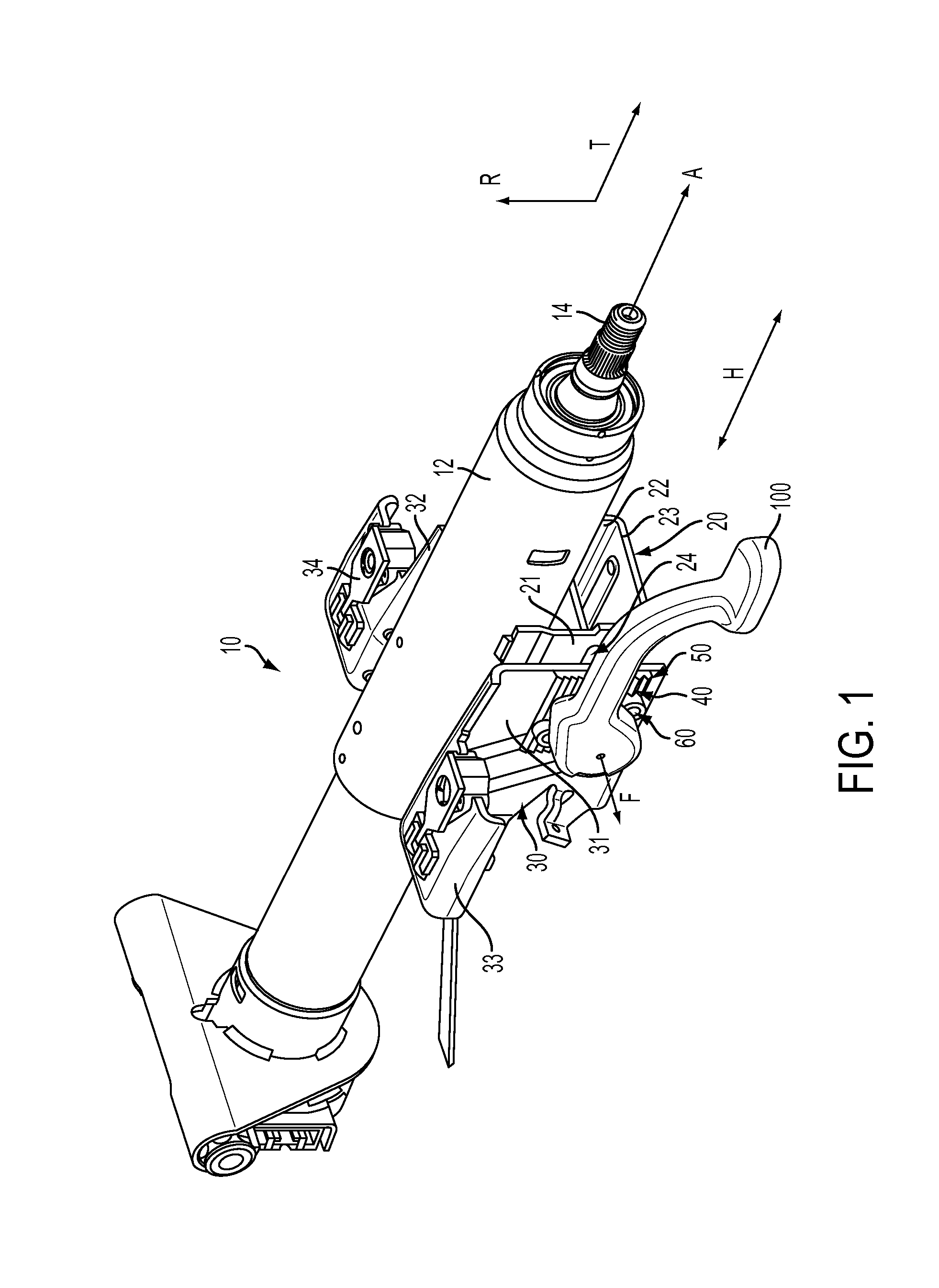
[0024]Referring now to the Figures, where the invention will be described with reference to specific embodiments, without limiting same, FIG. 1 shows an adjustable steering column of a vehicle in accordance with an exemplary embodiment of the present invention.

[0025]With reference to FIGS. 1 and 7, the adjustable steering column 10 includes a column jacket 12 housing a steering shaft 14 extending along a first axis ‘A’, a compression bracket 20 and a mounting bracket 30. The steering shaft 14 is connected to a steering wheel (not shown) at a first end and steering components (not shown) at a second end. The steering shaft 14 is configured to transfer rotation of the steering wheel by an operator of the vehicle to the steering components. The steering shaft 14 may be adjustable in a rake direction ‘R’ and / or a telescope direction ‘T’.

[0026]The compression bracket 20 is fixed to the column jacket 12 and is movable with the column jacket during adjustment of the steering column 10. The...


PUM


Abstract

A lock for an adjustable steering column includes a rotatable locking lever to actuate the lock between an unlocked position and locked position, a lock plate including plate lock teeth and a first slot, and a slider including slider lock teeth and a second slot angled relative to the first slot. The slider teeth are received between respective plate lock teeth. A lock bolt rotates with the locking lever and extends through the first and second slots, and has a retainer on one end. A cam positioned on the lock bolt applies or releases a force to the slider in response to rotation of the locking lever to actuate the lock. In the locked position the slider lock teeth lockingly engage between the plate lock teeth, and in the unlocked position, the slider lock teeth are released from locking engagement with and are positioned between the plate lock teeth.

Description

BACKGROUND OF THE INVENTION[0001]The following description relates to a lock for an adjustable steering column, and in particular, a rake and / or telescope lock in an adjustable steering column.[0002]Steering columns in vehicles may be adjustable in a rake direction and a telescope direction. The adjustable steering column may be unlocked in order to be adjusted to a desired position. Once the desired position is reached, the steering column may be locked in place to resist movement from the desired position.[0003]A traditional adjustable steering column may include a column jacket, a compression bracket fixed to and movable with the column jacket and a mounting bracket fixed to the vehicle. The column jacket and compression bracket are movable relative to the mounting bracket. The adjustable steering column may further include a locking lever, a rake lock and a telescope lock.[0004]The locking lever is rotatable between a locked position where adjustment of the steering column is re...

Claims


Application Information

Patent Timeline
Patent Type & Authority Patents(United States)
IPC IPC(8): B62D1/18
CPCB62D1/184
Inventor BUZZARD, DONALD A.ANSPAUGH, MICHAEL P.
Owner STEERING SOLUTIONS IP HLDG
Features
  • R&D
  • Intellectual Property
  • Life Sciences
  • Materials
  • Tech Scout
  • Unparalleled Data Quality
  • Higher Quality Content
  • 60% Fewer Hallucinations
Learn More