
Yard hydrant locking collar

a technology for locking collars and hydrants, which is applied in the direction of keyhole guards, mechanical control devices, instruments, etc., can solve the problems of easy cutting of the inability to easily cut seven-sixteenths hardened steel locks, and the chain used to complete the prior art locking mechanism is quite vulnerable to defeat by simple bolt cutters or hacksaws

Active Publication Date: 2014-11-25
DOUBLE H VENTURES LLC
View PDF19 Cites 6 Cited by
  • Summary
  • Abstract
  • Description
  • Claims
  • Application Information

AI Technical Summary

Benefits of technology

The invention is a locking collar for outdoor hydrants that prevents vandalism. The collar is made of hardened steel and has two mirror-image plates that are hinged at one end. The plates can be opened and closed around the hydrant to secure it. The collar can accommodate different sizes of hydrant pipes and is designed to prevent the hydrant handle from being lifted. The technical effect of this invention is to provide a secure and effective way to prevent vandalism on outdoor hydrants.

Problems solved by technology

Outdoor hydrants are very vulnerable to vandalism.
While a seven-sixteenths hardened steel lock cannot be easily cut, the chain used to complete the prior art locking mechanism is quite vulnerable to defeat by simple bolt cutters or hacksaws.
Milbeck is a complete locking cap and is not designed nor does it teach a structure for a hydrant valve having a locking hole in the end of the handle.

Method used


Image

  • Yard hydrant locking collar
  • Yard hydrant locking collar
  • Yard hydrant locking collar

Examples


Embodiment Construction

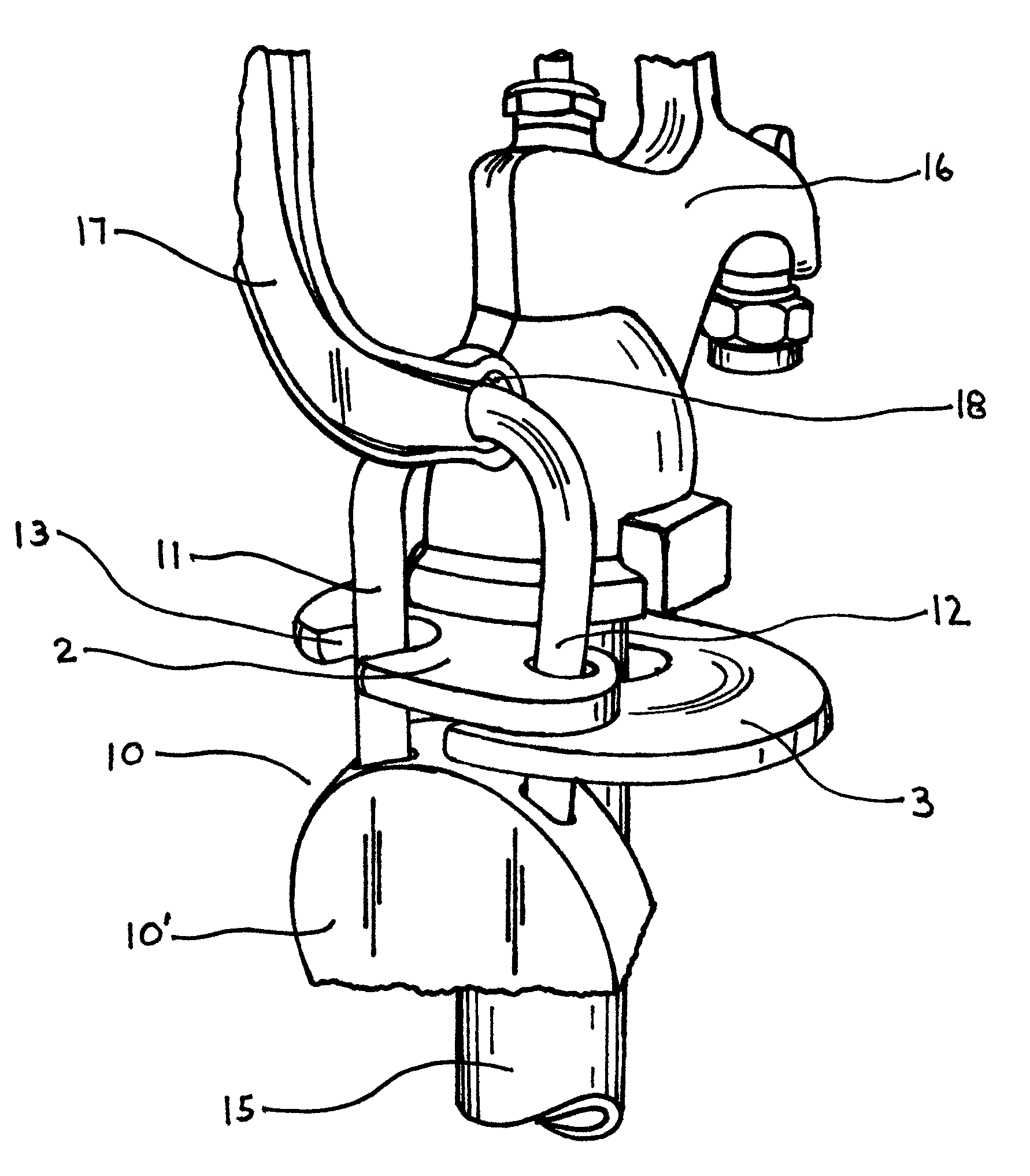
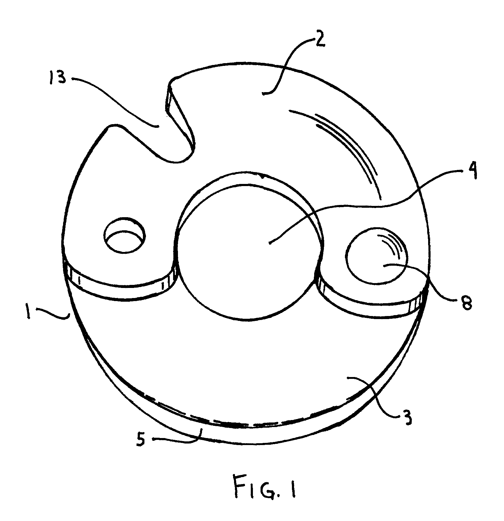
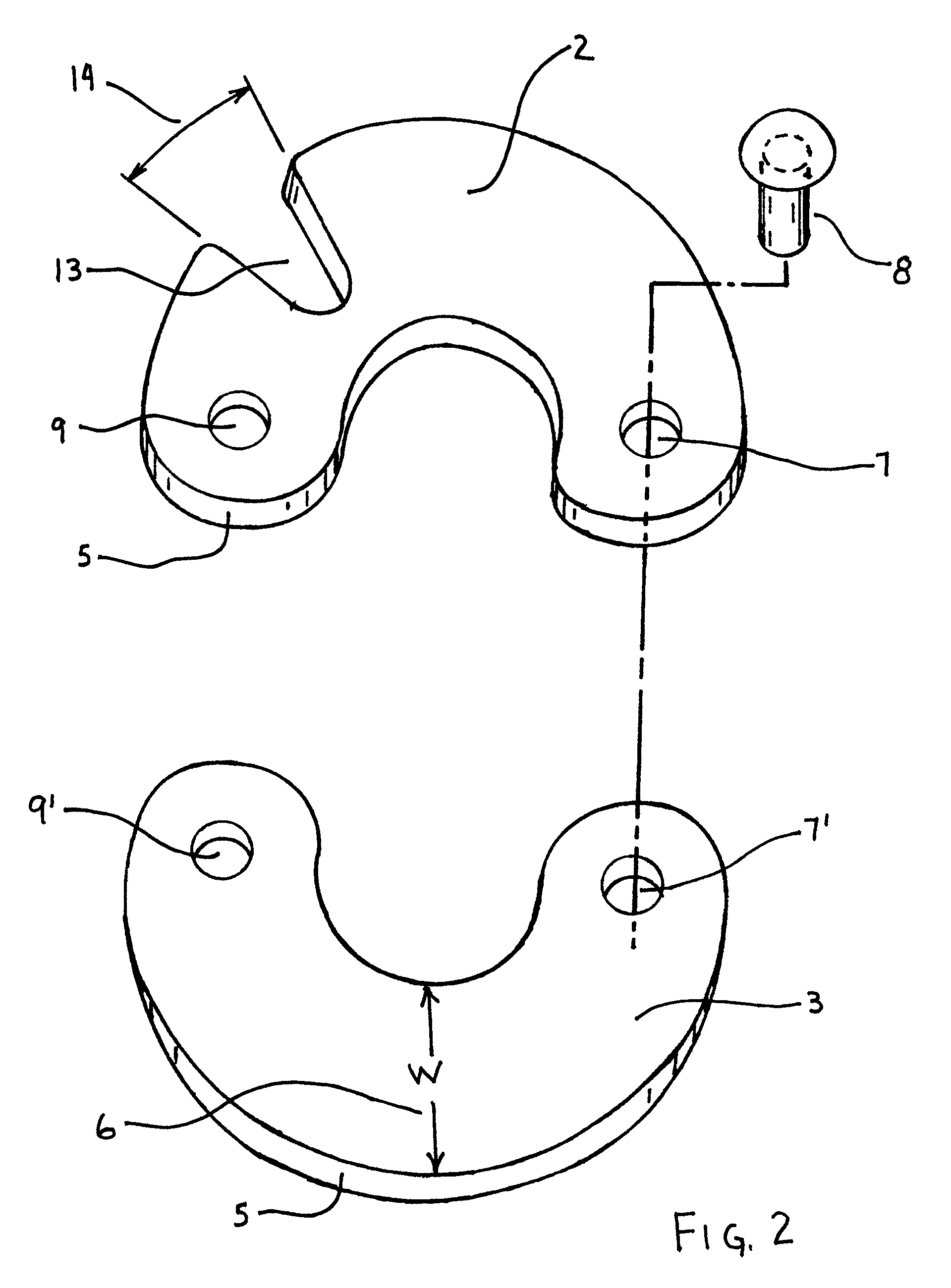
[0015]A yard hydrant locking device 1 comprises two essentially C-shaped crescents sections or plates. Top 2 and bottom 3 C-shaped crescents each have an essentially semi-circular outer perimeter and an essentially semi-circular inner perimeter as best shown on FIGS. 1 and 2. The upper 2 and lower 3 crescents pivot about the pivot pin 8 to form an inner hydrant pipe receiving hole 4 when the top and bottom crescents are closed and locked.

[0016]The diameter of the inner hydrant pipe hole 4 is approximately one and three-fourths inches in the preferred embodiment and is designed to receive hydrant pipes of that dimension. The inner hydrant pipe hole 4 can vary to accommodate other sized pipes while still keeping within the spirit and disclosure of this invention. The upper 2 and lower 3 crescent shaped plates have a width W, shown as number 6 on Drawing FIG. 2. The radius of pipe hole 4 is approximately seven-eighths inches. The total diameter of the connected plates from the center i...


PUM


Abstract

A yard hydrant locking collar has two C-shaped steel hardened plates connected together at one end by a rivet. The rivet acts like a hinge and allows the top and bottom plates to swivel open and closed. The other end of each top and bottom plates has a locking hole. A one inch tapered slot is cut into the top plate near the locking hole. The top and bottom plates are rotated so the collar fits around the hydrant pipe. The locking holes and slot are positioned near the hydrant locking hole and the collar locking holes are aligned. A padlock is opened and tilted away from the pipe and the free arm of the padlock is placed through the locking hole of the hydrant handle and positioned over the locking holes of the collar. The padlock is then tilted back towards the pipe. The tapered slot allows the padlock to move towards the pipe so that the free end of the padlock can move through the locking holes. Once the free end of the padlock passes through the collar locking holes, the padlock can be raised and locked. The locking collar and hydrant handle are thus locked together to prohibit movement of the handle.

Description

BACKGROUND OF THE INVENTION[0001]Outdoor yard hydrants were developed for residential, commercial and agricultural uses. Water pipes are usually positioned vertically to the ground. The pipe is capped off with a hydrant head. The hydrant head containing the water valve is usually operated by lifting a handle and pulling it away from the pipe to discharge the water. These hydrants are modeled after hand pumps from a prior era.[0002]Outdoor hydrants are very vulnerable to vandalism. According to most manufacturers, a chain and padlock is the most common method of securing and locking the hydrant handle to the water pipe. The end of the handle has a locking hole. One places a chain around the pipe and then positions the lock through the locking hole on the handle, thus preventing anyone from raising the handle away from the pipe and opening the water valve. While a seven-sixteenths hardened steel lock cannot be easily cut, the chain used to complete the prior art locking mechanism is q...

Claims


Application Information

Patent Timeline
Patent Type & Authority Patents(United States)
IPC IPC(8): F16K35/00E05B17/00
CPCE05B17/00Y10T70/5637Y10T70/5624Y10T70/5779Y10T70/40F16K35/10Y10T137/7069Y10T70/5739Y10T70/409E05B67/383
Inventor NIEMI, CARL, H.
Owner DOUBLE H VENTURES LLC
Features
  • Generate Ideas
  • Intellectual Property
  • Life Sciences
  • Materials
  • Tech Scout
  • Unparalleled Data Quality
  • Higher Quality Content
  • 60% Fewer Hallucinations
Learn More