

Bending joint mechanism, surgical instrument having this bending joint mechanism, and manipulator having this bending joint mechanism
a technology of bending joint and manipulator, which is applied in the field of bending joint mechanism, surgical instrument manipulator having this bending joint mechanism, which can solve the problems of durability, maintenance and controllability, and the difficulty of transmitting power through the bending joint portions to farther joints
- Summary
- Abstract
- Description
- Claims
- Application Information
AI Technical Summary
Benefits of technology
Problems solved by technology
Method used
Image

Examples
first embodiment
[0039](Configuration)
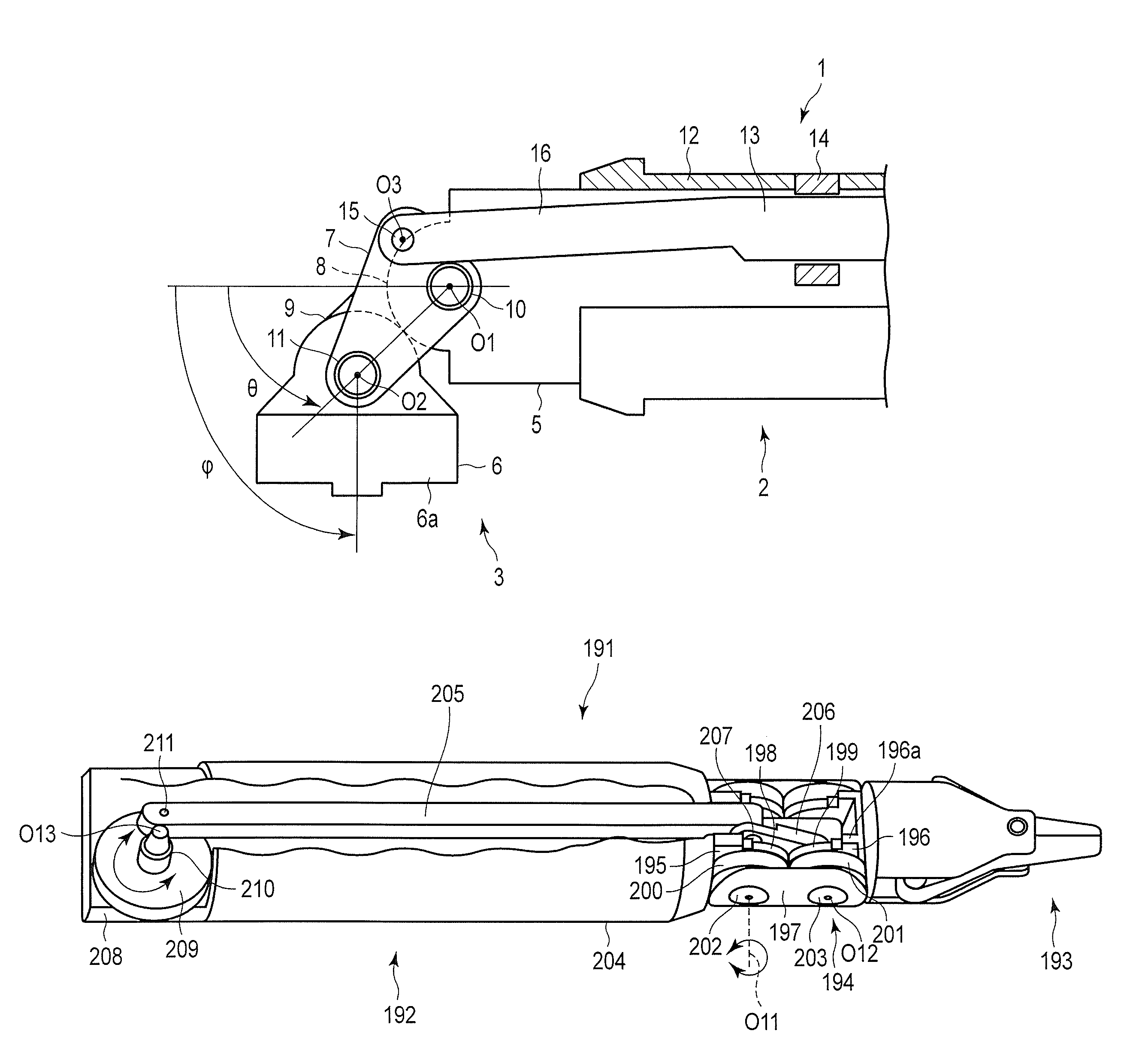
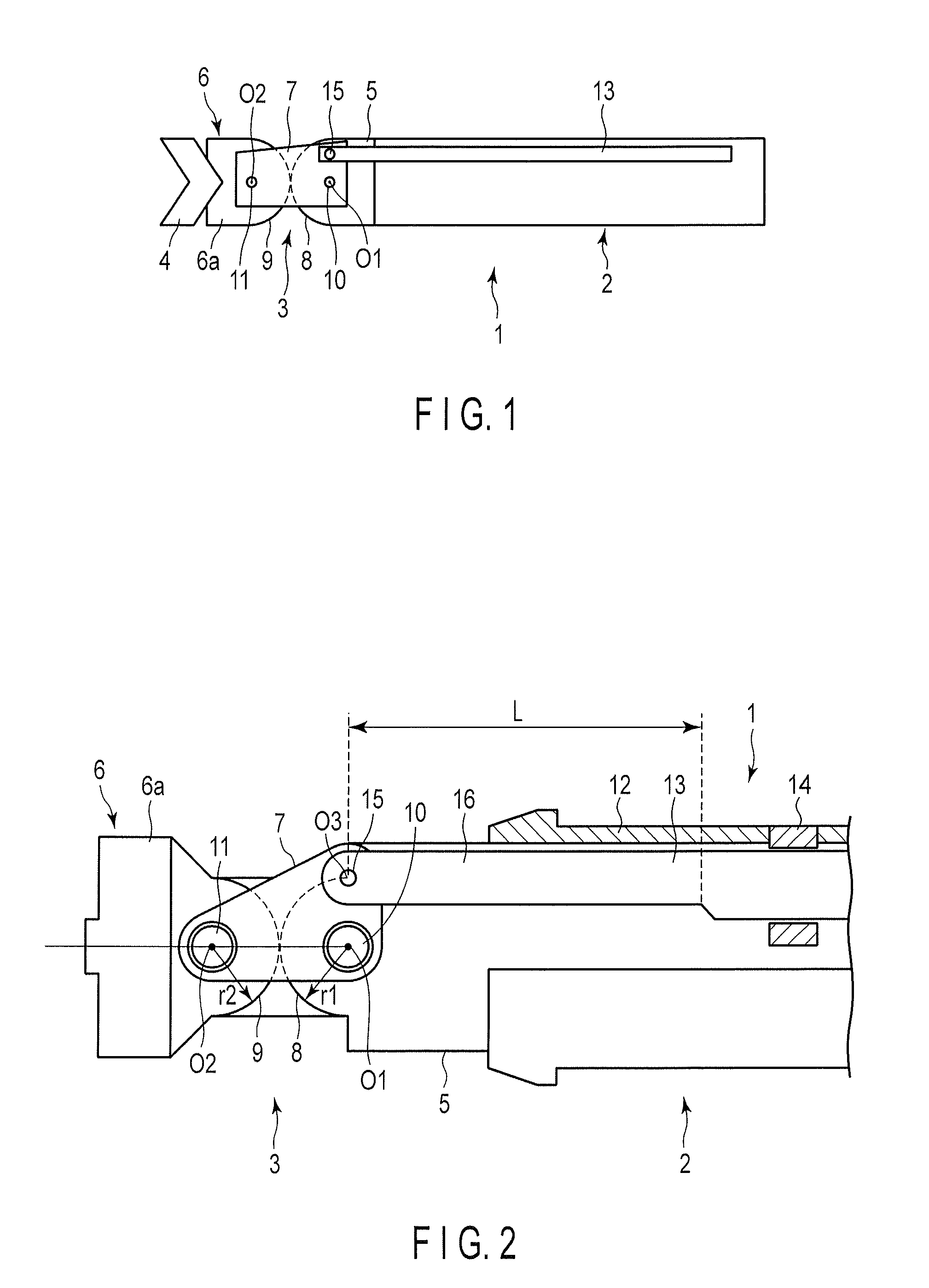
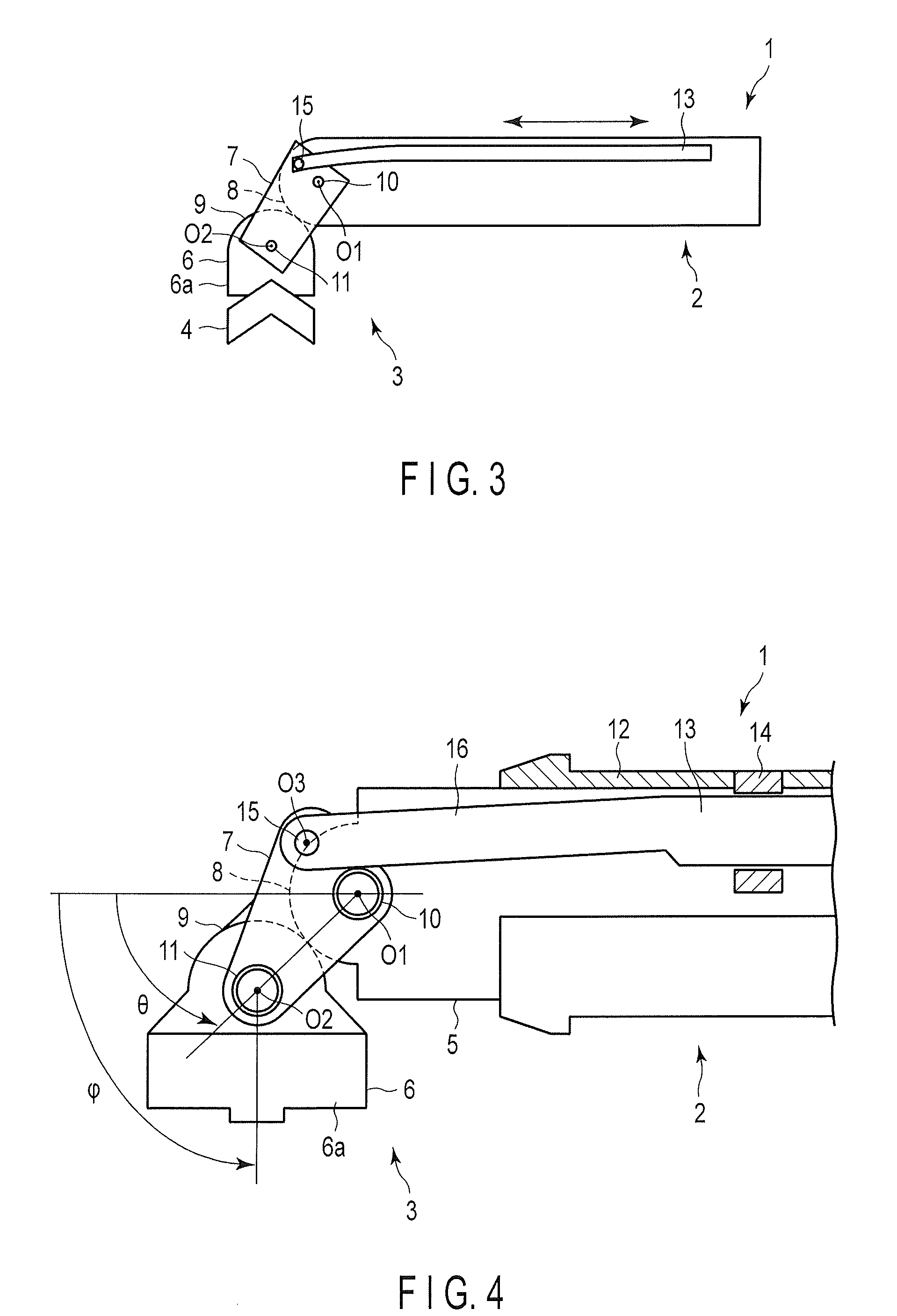
[0040]FIG. 1, FIG. 2, FIG. 3, FIG. 4, FIG. 5A, and FIG. 5B show the first embodiment of the present invention. FIG. 1 is a side view showing the overall general configuration of a treatment instrument 1 such as a multidegree-of-freedom surgical instrument according to the first embodiment of the present invention. A bending joint mechanism in a joint drive device of the treatment instrument 1 according to the present embodiment is coupled to the distal end of a shaft section 2 and a treatment portion 4 via a joint section 3 having a double joint mechanism. The bending joint mechanism bends the treatment portion 4 relative to the distal end of the shaft section 2 by the joint section 3.
[0041]The joint section 3 has the shaft section 2, a support section 5 provided at the distal end portion of the shaft section 2, an actuating section 6 coupled to the treatment portion 4, a drive plate section 7 which functions a coupling member to couple the support section 5 to ...
second embodiment
[0073](Configuration)
[0074]FIG. 7, FIG. 8, FIG. 9A, and FIG. 9B show the second embodiment of the present invention. According to the present embodiment, a first joint section (first joint section) 22 and a second joint section (second joint section) 23 are provided side by side at the distal end portion of a treatment instrument 21. The first joint section 22 and the second joint section 23 each have a double joint mechanism. The first joint section 22 and the second joint section 23 are substantially similar in configuration to the joint section 3 according to the first embodiment. The second joint section 23 is provided side by side with the first joint section 22 along the axial direction of a shaft section 24 (first shaft section), disposed forward of the first joint section 22, and coupled to an actuating section 6 (first actuating portion) of the first joint section 22.
[0075]As shown in FIG. 6, the treatment instrument 21 has the first joint section 22 and the second joint se...
first modification
of Second Embodiment
[0097]FIG. 10A shows a first modification of the second drive rod section 40 according to the second embodiment of the present invention. According to the present modification, the shape of the spring link of the second drive rod section 40 according to the second embodiment is changed as follows: A drive rod section 51 according to the present modification has a rod body 51a which is rectangular in section. The rod body 51a is provided with a first through-hole portion 52 and a second through-hole portion 53 that constitute an elastic part. The first through-hole portion 52 is disposed to perforate between one pair of opposite side surfaces (e.g., the upper surface and the lower surface) of the rod body 51a. The second through-hole portion 53 is disposed to perforate between the other pair of opposite side surfaces (e.g., the left surface and the right surface) of the rod body 51a. The first through-hole portion 52 and the second through-hole portion 53 are long...
PUM
 Abstract
Description
Claims
Application Information