Manipulator for medical use

a manipulator and medical technology, applied in the field of manipulators for medical use, can solve the problems of difficult visual confirmation of the amount of rotation in the gripper portion, and the inability to clearly image the gripper portion at the tip end, so as to achieve the effect of easy confirmation of the rotational angl

Active Publication Date: 2019-04-02
KARL STORZ GMBH & CO KG
View PDF19 Cites 638 Cited by
  • Summary
  • Abstract
  • Description
  • Claims
  • Application Information

AI Technical Summary

Benefits of technology

[0013]One aspect of the present invention is made in view of the above problems and an object of the aspect of the present invention is to provide a manipulator for medical use, in which an operator can easily confirm a rotational angle of a rolling mechanism, even when a gripper portion at the tip end cannot be confirmed clearly by an endoscope or even when the rolling mechanism has rotated 180° or more.
[0015]According to the rotation identifier, even when a gripper portion at the tip end cannot be clearly confirmed, or even when the rolling mechanism has rotated 180° or more, an operator can easily confirm a rotational angle of the rolling mechanism.

Problems solved by technology

The long incision site can be a significant concern because it is subject to infection and is often the most traumatic and painful part of the patient's recovery.
However, a gripper portion at the tip end is not necessarily imaged clearly.
Also, since the gripper portion is often vertically symmetric, when the gripper portion is rotated 180°, the amount of rotation in such a gripper portion may be difficult to visually confirm.

Method used


Image

  • Manipulator for medical use
  • Manipulator for medical use
  • Manipulator for medical use

Examples


Embodiment Construction

[0029]Manipulators for medical use according to preferred embodiments of the present invention shall be described below with reference to FIGS. 1 through 10.

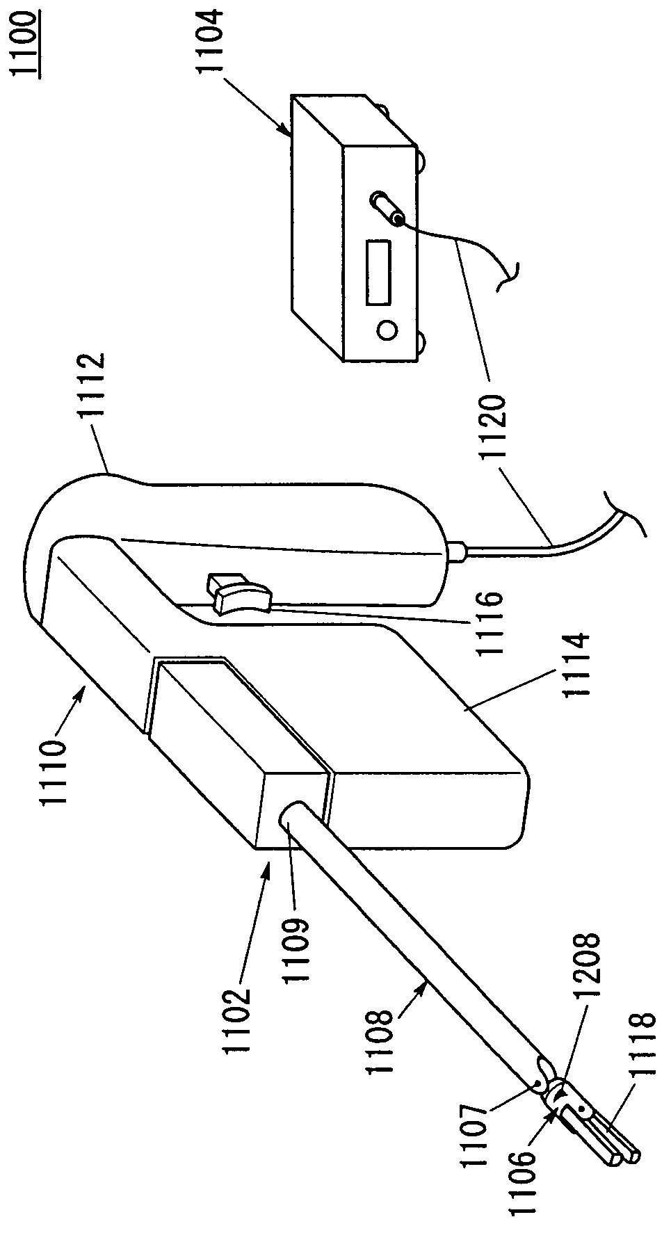
[0030]With reference to FIG. 1, a perspective view of a manipulator system for medical use 1100 is shown. The manipulator system 1100 may include a manipulator 1102 and control electronics 1104. The manipulator 1102 may include a working unit (working mechanism) 1106, a hollow shaft 1108, and a working unit control mechanism 1110. The shaft 1108 has a first end 1107 and a second end 1109 opposite to the first end 1107. In general, the shaft 1108 includes an elongate tube through which control cables (power transmitting member) extend. The control cables operably couple the working unit 1106 with the working unit control mechanism 1110. The working unit 1106 mounts to the first end 1107 of the shaft 1108 using a variety of mechanisms as known to those skilled in the art both now and in the future. The working unit control mechani...


PUM


Abstract

A manipulator comprises a hollow shaft, wires provided on the shaft and a working unit disposed on one end of the shaft and being driven by at least one wire of the wires, the working unit having a tip tool including a rolling mechanism which rotates about an axis Or directed to a distal end thereof. A tip side surface of a proximal end member and a cover of a distal end member are relatively rotated by the rolling mechanism. The cover has a rotation identifier for indicating a degree of relative rotation of the tip side surface. The tip side surface has an alignment indicator for indicating an initial position of the cover.

Description

BACKGROUND OF THE INVENTION[0001]Field of the Invention[0002]The present invention relates to a manipulator for medical use, and particularly to a manipulator for medical use having a tip tool including a rolling mechanism rotatable about an axis which is directed to a distal end thereof.[0003]Description of the Related Art[0004]When surgery is traditionally performed, there is a long incision made so the surgeon can view and repair the internal parts of the patient. The long incision site can be a significant concern because it is subject to infection and is often the most traumatic and painful part of the patient's recovery. In recent years, many surgeons have been using endoscopic tools and performing minimally invasive surgery, thereby vastly reducing the size of the incision.[0005]A manipulator system is composed of a manipulator body and a controller therefor, as described in Japanese Laid-Open Patent Publication No. 2004-105451, for example. The manipulator body contains an o...

Claims


Application Information

Patent Timeline
Patent Type & Authority Patents(United States)
IPC IPC(8): A61B17/29A61B34/00A61B17/00A61B34/30A61B90/00
CPCA61B17/29A61B34/70A61B34/71A61B34/30A61B2090/0811A61B2017/2926A61B2017/2927A61B2034/742A61B2017/00455
Inventor OMORI, SHIGERUUENOHARA, SHUICHIJINNO, MAKOTOSUNAOSHI, TAKAMITSU
Owner KARL STORZ GMBH & CO KG
Why Eureka
Try Eureka